This thread has been locked.

If you have a related question, please click the "Ask a related question" button in the top right corner. The newly created question will be automatically linked to this question.

LDC1101: LDC1101

Part Number: LDC1101

Hello
We use the ldc1101 chip with an circular inductor coil. We need to olny measure the inductance change caused by the expansion and deformation of the inductor coil. We find that when the inductor coil does not have any deformation, we only move or flip the device and the coil in space. It also causes the ldc1101 output  a great change in inductance, we want to know what is the cause of this phenomenon and hope to solve it. Thank you.

We known that The LDC1101 output value is related to the coil itself and the medium around the coil. so our test is done far away from other objects, with the hands move or flip the coil and ldc1101 in the air.
Moreover, we use the 0805 surface-mount inductor instead of the coil, directly connected to the two input terminals of ldc1101, and to make the ldc1101 space move or flip at any time, and also cause a large change in the output inductor of the ldc1101.

  • Hi Huiwang,

    The movement and orientation of the inductor should not affect the resonant frequency if there are no targets present. The only exceptions are if you have a loose connection to the board or if the temperature is changing. I think it is more likely that something is influencing the capacitor. Could you tell me more about the capacitor you are using in the LC tank?

    Regards,

  • Hello, thank you for your reply.

    Our circuit diagram is as follows. Capacitance C141 is the shunt capacitance of the inductance coil, and its model is C0603C472F5GACTU. RIP+ and RIP- are two terminals connected to the external inductance coil, and the inductance coil is not shown in the diagram. When we do the experiment, the inductor is directly welded to RIP+, RIP-.Our initialization code is as follows

        LDC1101_WREG(LDC1101_CMD_START_CONFIG,0x01);
        LDC1101_WREG(LDC1101_CMD_DIGCONFIG, 0x93);
        LDC1101_WREG(LDC1101_CMD_ALTCONFIG, 0x01);
        LDC1101_WREG(LDC1101_CMD_D_CONFIG, 0x01);//01
        LDC1101_WREG(LDC1101_CMD_INTB_CONFIG, 0x00);
        LDC1101_WREG(LDC1101_CMD_LHR_RCOUNT_LSB, 0x00);
        LDC1101_WREG(LDC1101_CMD_LHR_RCOUNT_MSB, 0x14);
        LDC1101_WREG(LDC1101_CMD_START_CONFIG,0x00);

  • Hi Huiwang,

    Thank you for the additional information. The type of capacitor you are using is what we generally recommend, so I don't see an issue there. Could you also test whether the measurements are sensitive to touching the sensor capacitor or the sensor inductor? Just touching them with your hand would be enough.

    Regards,
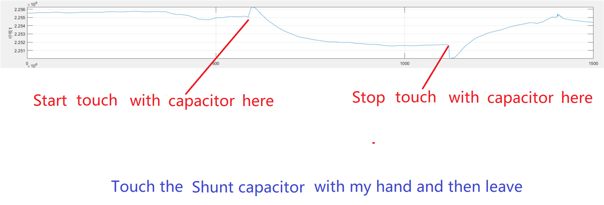
  • Hello, I did the experiment according to your suggestion. In the experiment, we replaced the actual coil sensor with the patch inductor model MLF2012A1R2J, and we did 4 experiments.

    Test 1: touch the inductor by hand.

    Test 2: touch the capacitance by hand.

    Test 3: blowing hot gas.

    Test 4: The circuit board and the inductor do linear reciprocating motion together.

    We use pictures to record each test process. See the back map. The horizontal coordinates of each map represent 40 milliseconds, and the ordinate represents the sample output of ldc1101.

  • Hi Huiwang,

    Thank you for providing such clear data. It definitely looks like you are experiencing capacitive effects. Multiple things could be causing this issue. There could be an aggressive electric field in the vicinity of your board that changes parasitic capacitance on your coil as you move it. To solve this I would suggest shielding the test area, possibly with a large grounded metal box.

    Regards,
  • Hi Huiwang,

    I haven't heard from you in a while, so I'm assuming you were able to resolve your issue. If this was not the case, please feel free to follow up in this thread or post a new question in the forum. We'd be happy to continue helping you debug your issue.

    Regards,
  • I'm sorry we haven't had any feedback for so long. We're still working on this problem. Our equipment is in the normal office environment. There is no obvious strong electric field disturbance around. According to your suggestion, we plan to put the ldc1101 equipment and inductance in a shielded box and do some tests again. In addition, we would like to know whether such problems can not be avoided in circuit design, assuming they are proved to be caused by external electric field interference.
  • Hi Huiwang,

    It is definitely possible to avoid EMI issues with careful PCB design. This app note has a lot advice for reducing EMI in inductive sensing systems. 

    Regards,