This thread has been locked.

If you have a related question, please click the "Ask a related question" button in the top right corner. The newly created question will be automatically linked to this question.

PGA411Q1EVM: PGA411-EVM board errors

Part Number: PGA411Q1EVM

Hi,

I am trying to communicate with TMS320F28379 Launchpad but I am not able to receive any SPI response back. I can see the solid green light and all the fields in GUI are right. Also, I tried to observe the SCLK, NCS, SDI signals on the EVM using CRO probe points provided. They are looking fine. Here is what I am doing right now.

I am not able to receive any SPI response and the receive buffer is always empty.
1. I am sending 1 byte at a time and repeating it 4 times
2. The clock frequency is 1 Mhz
3. I observed that the chip select is low for entire 32-bit transfer
4. Configured SPI as CPOL = 0 and CPHA = 1
5. I made sure NCS is kept high for 1ms between two SPI commands


I tried changing the J3 to both 3 and 5, 4 and 6 but there is no response. Is there anything that I am missing?

  • Bala,

    I'm a little confused, how are you using the GUI with the LaunchPad? Are you saying that the EVM + GUI is working, but when you try to control the PGA411 by connecting the launchpad SPI, it isn't working? Where are you connecting the LaunchPad signals to the EVM?
  • Hi Clancy,
    Sorry for the confusion . Yes I mean to say that EVM + GUI is working, but when I try to control the PGA411 by connecting the launchpad SPI, it isn't working. I am not able to see any SPI response from the EVM. The SPI receive buffer on the 320 launchpad is always empty. I am connecting the launcpad SPI signals to EVM SPI pins on J11 . I checked the connections and everything seems good. Also I am able to observe SCLK, NCS, SDI signals on the EVM using CRO probe points provided. They all look good.

    Here is a description of the steps that I am doing right now:
    1.Supplying 5-V to the banana connectors for VCC and GND
    2. Connecting EVM launchpad to PC and observing its status in GUI
    3.calling pga411_Init() and applying DELAY of 10ms
    4. Sending 32 bit SPI read message to read DEV_STAT5 register

    In addition to it I am doing all the SPI configs I mentioned above. Is there anything that I am missing?
  • Bala,

    Here are a couple of things to check:
    - Status of NRESET pin (I doubt this is the issue since the GUI appears to be functional, but if NRESET is low, you will not see any activity from
    - VIO voltage setting - make sure that jumper J3 is positioned appropriately to match the IO level of the C2000. You can choose between 1.8V, 3.3V, and 5V modes

    What is the SPI message that you are sending? Can you also attach a screenshot of the SCLK, NCS, and SDI waveforms?

    Thanks,

    -Clancy
  • Hi Clancy,

    I have checked the NRESET pin, it is logic high.I tried toggling the NRESET and able to observe the transition from low to high.

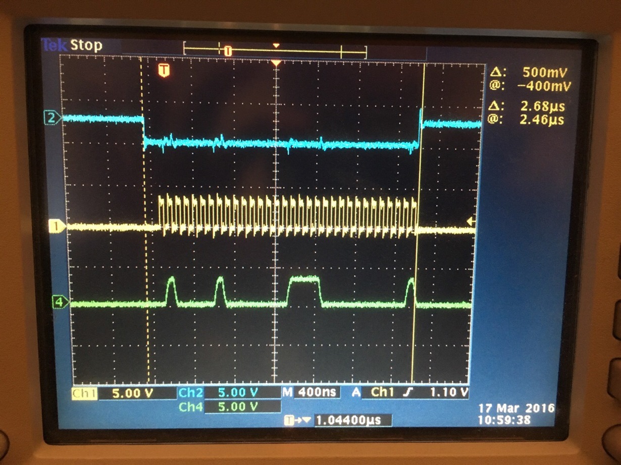
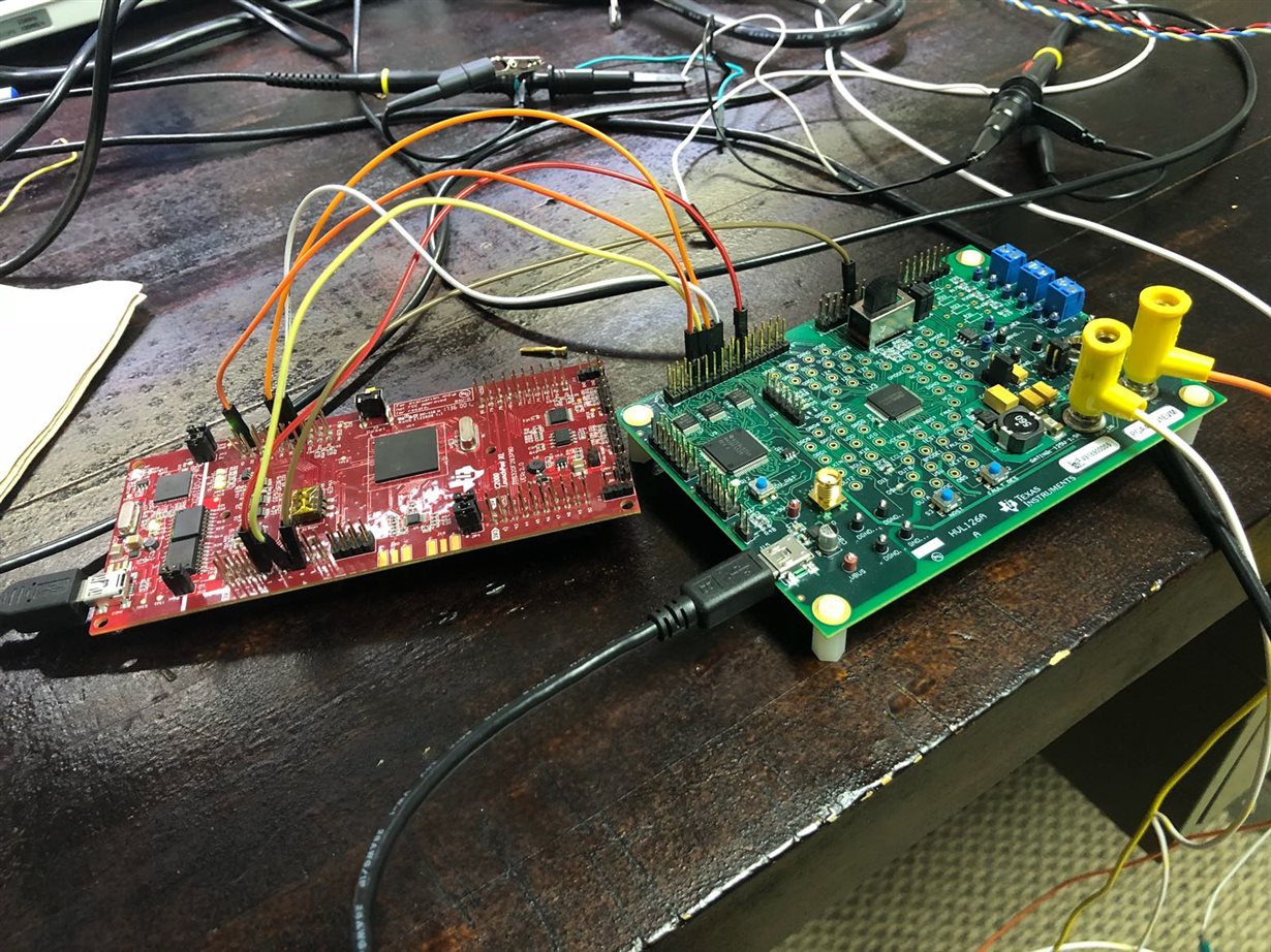
    My C2000 Launchpad is at 3.3v. So I let the j3 to stay at 3.3V.(3,4) . I tried changing  j3 to 5v(5,6) but no response yet.  You can find the screenshot of the SCLK, NCS, and SDI waveforms below and the board connections. I am sending the SPI message to read DEV_STAT5 register as 0x4100F001. 

  • Hi Clancy,
    Also I tried to write to registers from the GUI itslef.I changed the state to DIAG in GUI , write to one of the registers and tried to read it again.
    It is not reflecting the value I have written and showing the default value . Also the fault is getting reported in GUI, So I am making the FAULTRES pin OUT_LOW from the GUI to ignore faults.

  • Bala,

    It is interesting that in the GUI SPI read is working but not SPI write. It is not surprising that you are seeing faults since you do not have a resolver connected, but that should not impact SPI read/writes.

    From your waveform, it looks as if SDI might have too much of a load. Is there any capacitance on SDI on the Launchpad?

    Perhaps the level translator is impacting this. You might need to remove level translator U4. Of course, that would make it impossible to use the GUI anymore.

    I will find a Launchpad and run a couple of tests to recreate your set-up, but this will take me another few days. My apologies that this is taking some time to resolve.

    Thanks,

    -Clancy
  • Hi Clancy,

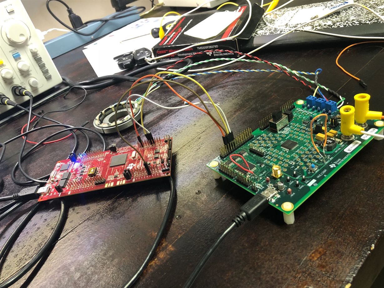
    Thanks for the response.  Now I have made some modification to the EVM by shorting the switches S2and S4. Now I am receiving a constant response from resolver as 0x23 all the time irrespective of the transmitted message. I am attaching an image of my EVM here for your reference.

    Regards,

    Bala.

  • Hi Clancy,

    After shorting the above switches s2 and s4 , Now I am able to communicate with EVM correctly.
    Thank you so much for your help. Now I will be working with implementing application and let you know if I have any questions.

    Regards,
    Bala.
  • Great! Thanks for letting me know.
  • Hi Clancy,

    I am now trying to read angle by connecting a 3 pole resolver . I kept the NPLE as 3. when I move the resolver through 360°, I get three cycles of 0-359°, instead of just one.
    I went through the below post but didn't understand what exactly I need to do
    e2e.ti.com/.../568047

    For accounting it in software I need to know the absolute postion of the resolver . I mean in which of the three parts the resolver is right now. Is there anyway of doing this ?

    Thanks,
    Bala.
  • There is no way to do this just from the PGA411's perspective. The PGA411 will see no difference between the three cycles. You will need to find the correct 120 degree window through a different means; however, I am not familiar enough with motor control systems to suggest the best way of doing so.