This thread has been locked.

If you have a related question, please click the "Ask a related question" button in the top right corner. The newly created question will be automatically linked to this question.

ADS1148: ADS1148 DOUT/DRDY# and DATA READ OPERATION

Part Number: ADS1148
Other Parts Discussed in Thread: ADS1248

I am Japanese. Explanation may be insufficient.

Operation is done by setting the 23rd pin (START) of ADS1148 to HI.

The operation differs when comparing the two ADS1148.

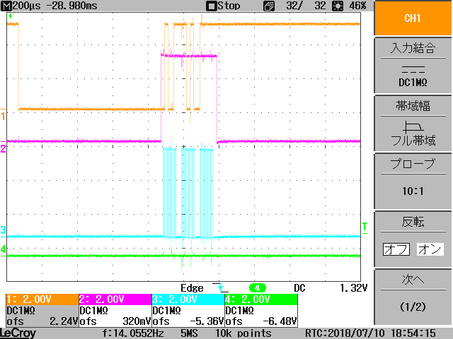
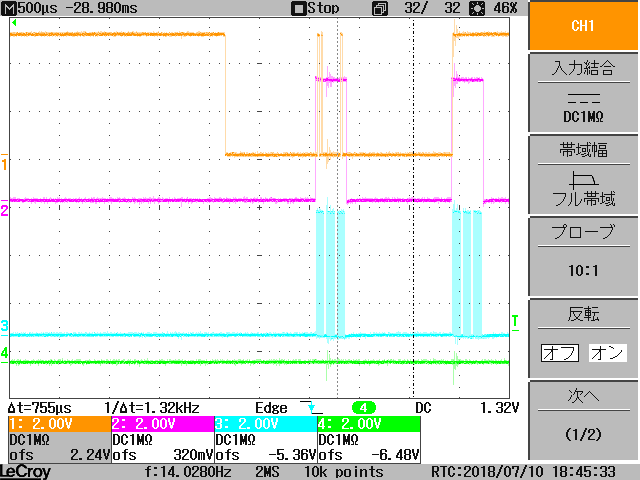
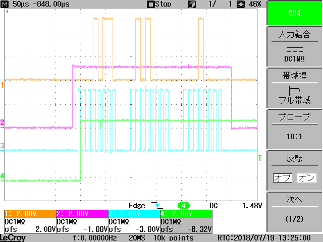
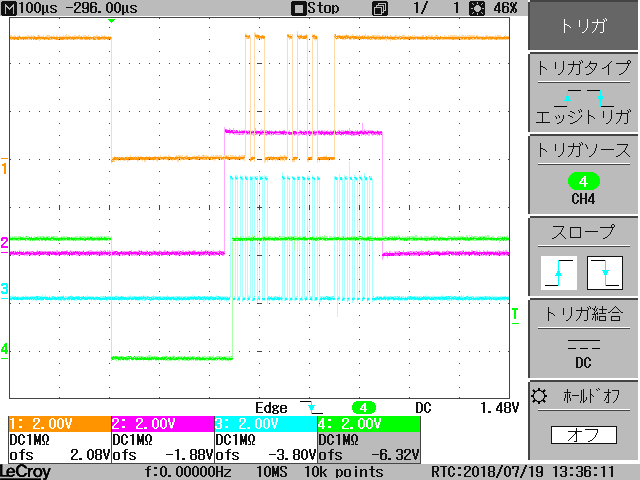
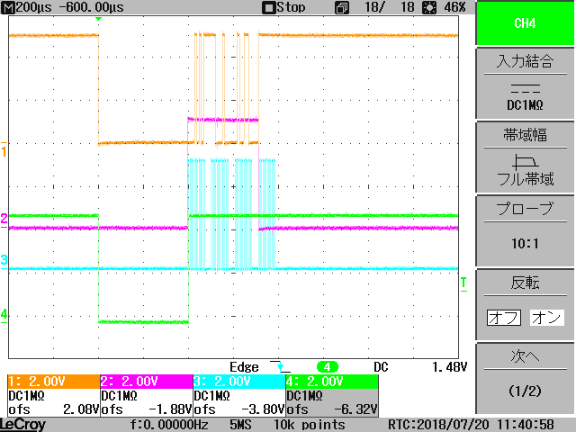
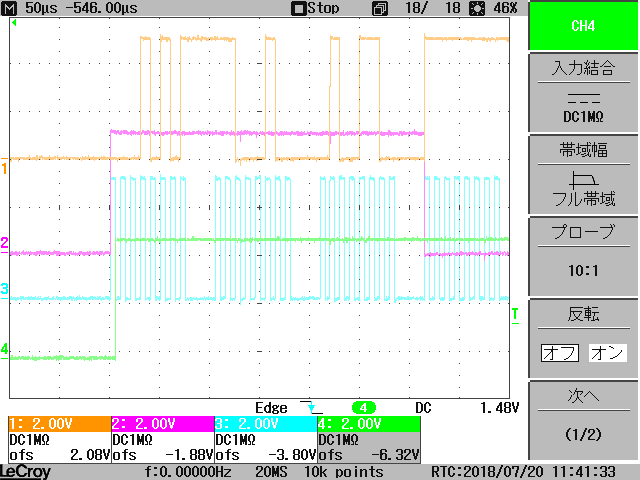
CH1(Yellow): MISO(DOUT/DRDY#) , CH2(RED):MOSI(DI)

CH3(BLUE):CLK, CH4(GREEN):CS

DRDY # is HIGH with the next NOP instruction after data output

DRDY # does not go HIGH with the next NOP instruction after outputting data.

DRDY # becomes HIGH with two NOP instructions.

Movement is different though it is the same model number
Which is the correct behavior?

After outputting data, DRDY # goes high at the next rising edge (CLK) and it was written in the data sheet.
It seems there are 24 bit data output even though it is a 16 bit product.

Why is DRDY # not going High at the next rise (CLK) after data output

  • Takashi-san,

    Normally, the first plot is close to how the device would operate with the combined DOUT/DRDY. However, the second looks wrong. First, you should make sure that you have your registers set up correctly. Do you have the DRDY MODE bit set high? Can you send me the register values for the ADC.

    I think this is a problem in the ADC readout timing. It's a little hard to see these plots because there's not enough detail to show DOUT/DRDY and SCLK. Instead of plotting the /CS line, can you plot the real /DRDY line?

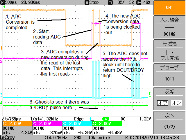
    Normally, you would use /DRDY as an interrupt. This way, the data is read from the ADC at the falling edge of /DRDY. However, if the data is read by just checking that the /DRDY (or the DOUT/DRDY) is low, then you don't know when the ADC completed the last conversion. If the conversion completes and you wait too long to read the data, then a new conversion may complete, interrupting the read of the data. In your second scope plot, I think this is what happens:

    To check this, look at comment 6 near the bottom of the scope shot. Plot /DRDY and find out when the new conversion comes out. You should be able to see the /DRDY go and stay high.

    To avoid getting interrupted by a new conversion, you could set the device in SDATAC mode, so that a new conversion does not update DOUT. Then you would use the RDATA command to read out the device.

    Read through my comments and then test the device to see if this is the problem.

    Joseph Wu

  • Joseph-san

    The first and second plots are running with the same firmware.
    The difference is the time to purchase the device.

    START PIN is set to High and / DRDY is used with open.
    The DRDY MODE bit is set to high.

    ・Operational flow
    CS = LOW
    while( DOUT/DRDY#  == HIGH )
    get data  CLK =16bit 
    send nop CLK = 8bit


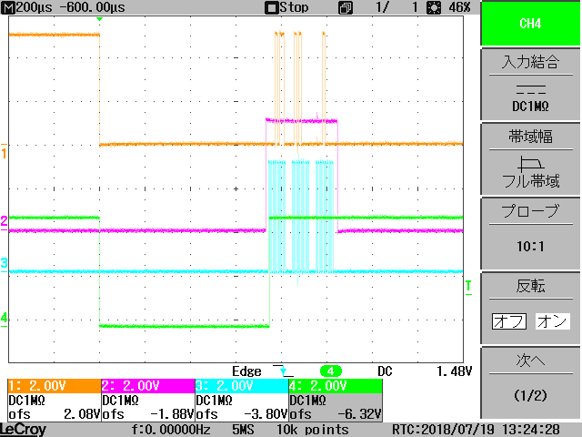
    / DRDY triggered plot.

    CH1(Yellow): MISO(DOUT/DRDY#) , CH2(RED):MOSI(DI)

    CH3(BLUE):CLK = 98kHz, CH4(GREEN):/DRDY

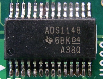
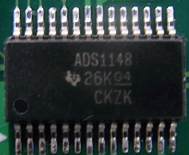
    Device photo

    Device that DOUT / DRDY goes HIGH at the next clock after acquiring 16 bit data.

    In the data sheet, it is written that DOUT / DRDY # goes HIGH at the next clock after data acquisition.
    In fact, is not it necessary to keep sending the clock until DOUT / DRDY # goes HIGH?

  • Takashi-san,


    Thanks for the new plots. The close-up view makes it easier to see the SPI communications.

    At this point I'm not sure what the problem is. When clocking out the data, you would use 16 SCLKs. If the device has not completed a new conversion and if the DRDY MODE bit is high, a 17th SCLK forces DOUT high and it stays high until a new conversion completes. In your first post, it was hard to see the details. In the new close up post, it doesn't look like there is any interruption from a new conversion and it looks like the wrong behavior for this device.

    Can you provide the complete register configuration for the device? I want to check through the setup and want to know what is written to the device before this occurs. To be sure, I want to know that the DRDY MODE bit is set high and that the device is in a read data continuous mode.

    Do you believe that this problem is just with this date code of the device? How many devices show this behavior is it all with this date code? To be clear, is the device with the error lot coded A38Q or is the error with CKZK? For the devices shown it looks like the dates from the devices are December 2016, and June 2012. From which distributor did you receive the devices with the error.

    I've checked and the last changes to this device were made in 2012. This was for an sensitivity at cold temperatures in level shifters between different sections of the device. The behavior of the device should not have changed, even before the 2012 revision.

    Are you able to alter your firmware to run some tests? It would be a good test to clock in four bytes (32 SCLKs) instead of three bytes (24 SCLKs) just to check the behavior. The behavior shown looks similar to the behavior of the ADS1248. The ADS1248 is the 24-bit version of the ADS1148.


    Joseph Wu

  • Joseph-san

    > Can you provide the complete register configuration for the device?
    register setting
    POWER ON
    RESET COMMAND
    IDAC0 <- 0x08
    MUX 0 <- 0 × 04
    MUX 1 <- 0 × 30
    SYS0 <- 0x03

    >Do you believe that this problem is just with this date code of the device?
    >How many devices show this behavior is it all with this date code? To be clear, is
    >the device with the error lot coded A38Q or is the error with CKZK?
    >For the devices shown it looks like the dates from the devices are December 2016,
    >and June 2012. From which distributor did you receive the devices with the error.

    The error rod is A38Q.

    Purchase bought 205 pieces with digikey unofficial market.
    ADS1148 6BK-A38P @ 150
    ADS1148 6BK-A38Q @ 60
    ADS1148 6AK-A6L3 @ 5

    I tested each one.
    Each lot is NG.

    I changed the firmware and tried 4 bytes (32 SCLK).
    It is similar to ADS1248.

    CH1(Yellow): MISO(DOUT/DRDY#) , CH2(RED):MOSI(DI)
    CH3(BLUE):CLK = 98kHz, CH4(GREEN):/DRDY


  • Takashi-san,


    I'm checking into the lot trace codes for the devices that you have. However, I won't be able to get more information about them until next week.

    If none of your new devices behave as expected, then I think you may need to return these devices to Digikey so that we we can start an official failure analysis. It's possible there was some problem in the final test, and it will take some time to figure out where the problem came from. If you return the devices, we will be able to retest them.

    I'll find out more information about the lot trace codes next week and I will post back or contact you through email if that is acceptable.


    Joseph Wu

  • Joseph-san

    I think that I will return the purchased parts.

    Thank you for many advice.

    I will wait for an e-mail
  • Takashi-san,


    I will take this post offline.

    I've been doing some research on the final test and will contact via email soon.


    Joseph Wu
  • Takashi-san,


    I have sent you an email and you can now contact me through my email.


    Joseph Wu
  • OK.
    I will contact you by email.