This thread has been locked.

If you have a related question, please click the "Ask a related question" button in the top right corner. The newly created question will be automatically linked to this question.

TVP5150AM1 output problem

Other Parts Discussed in Thread: TVP5150AM1, TVP5150

I'm interfacing TVP5150AM1 with a Cypress FX3 . I2C seems to function well and outputs are not high impedance but they output values that look quite nonsensical. I get all logic ones on YOUT4 and YOUT7 which result in dark violet color. Nothing changes when I try to force a black screen, the same values are even outputed during vertical or horizontal blanking periods.

To make things more clear, I will tell registers and their values:

Register -- Value

0x00 -- 0x08

0x03 -- 0xAF

0x06 -- 0x07

0x0D -- 0x40

0x0F -- 0x06

0x12 -- 0x04

  • Make sure that those pins are configured as INPUT on the Cypress device.

    Something else in your system is pulling those signals high.

    As a test you can disable the data outputs on the TVP then try pulling each signal low with a 1K resistor. If you can't pull the signal low through a resistor then something else in your system is definitely pulling the signals high. As a final test you can either remove the TVP or lift the device pins so they are not connected to the PCB and repeat the tests.

    Do you see the same result on multiple boards? If you have only tested one system then it could also be a short somewhere on your PCB.

    BR,

    Steve

  • As I see, I probably described my problem too vaguely. Output pins mentioned aren't always high, voltage levels aren't constant, they look like normal video signals and are of 13.5 MHz frequency. So I don't think it something else pulling pins high, it's probably programming or schematics or PCB layout

    I used ribbon cable at the beginning to connect FX3 Superspeed DevBoard and custom made PCB board with TVP5150AM1 but there was too much noise so I got rid of it and noise problem got better.
  • From a programming perspective the outputs are either driving or tri-state. If you see them changing then they are enabled as outputs.

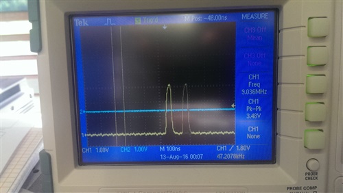
    Can you share an oscilloscope capture of the 'bad' pins and also 'good' pins at the TVP side of the connections and also at the Cypress end? Captures for the clock would also help.

    How long is your ribbon cable?Do you have enough ground connections in the cable (ideally should be one for every signal)

    BR,
    Steve
  • I got rid of ribbon cable and pins now mate without it. As it is SuperSpeed Explorer Kit, ribbon cable is not really needed and result is less noise which is appreciated but problems persist.


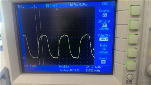
    SCLK signal:

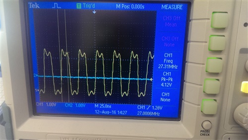
    YOUT4 and YOUT7:

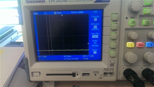
    Rest of outputs:

    Now contacts are mated using 0.254 mm pitch connectors. To really make sure that Cypress Device doesn't do anything I will try to get some jumper wires in several days and connect only voltage rails and I2C and share results. Do you have any ideas in the meantime?

    Update:

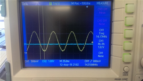
    Measured at XTAL1/OSC_IN:

    This crystal is 14.31818 MHz +-30ppm, so drift is bigger than it should be.

    I also found that putting Cypress to RESET state changed nothing so problems with it look highly unlikely to me

  • If you enable the TVP outputs then they should toggle.

    Try leaving all TVP registers in their default state and ONLY enabling the clock & data outputs so that the device is in ITU656 mode.

    In ITU656 mode there should be transitions on all data signals at some point due to the embedded sync codes (0x00 & 0xff).

    If you do not see all signals transitioning at some point then you either have a damaged TVP or something in your circuit is pulling the data signals.

    BR,
    Steve
  • They all toggle at some point:

  • OK, so if they all toggle then the TVP outputs are configured correctly.

    I thought you said they were not toggling?

    Are you sure you have configured the Cypress device correctly?

    Magenta images often implies the receiver is configured for the wrong color format.

    BR,
    Steve
  • I soldered new custom board and disconnected output pins from Cypress altogether expecting that it was all Cypress's problem. I only left SCL and SDA for I2C and voltage rails. Turns out nothing changes - outputs toggle if I add embedded codes but outputed values don't change if I try to force black color - YOUT4 and YOUT7 are toggling at 13.5 MHz frequency. I will try to connect a camera later but I don't expect anything to change.

    I could add schematics if that 'd help

  • Do you have a video source connected? (you say "I will try to connect a camera later").

    With no video source connected the output will be black.

    BR,

    Steve

  • I haven't plugged in camera yet, so yeah, it's strange for me that output is not black (Black is RGB 0 0 0 or YUV 0 128 128)
  • You will see some different values due to the sync codes which are embedded in the stream.
  • Even at 8-bit 4:2:2 YCbCr with discrete sync output? I'm sorry that I don't undestand whole concept. What I'm trying to achieve is only "useful" data through data lines, synchronisation would be performed using hardware synchronisation signals (VBLK, etc.). As black is YUV 0 128 128, I should see zeroes half of the time on YOUT7? So toggling on this would make a lot of sense and I'm just not understanding whole concept?
  • The default mode is ITU656 output, which contains synchronization codes.

    How are you configuring the Cypress device?

    My suggestion is to use ITU656 mode.

    Have you actually configured the Cypress device and started to receive digital video, or are you simply looking at the digital data and trying to determine what you expect to see?

    I think you might be over thinking this. Don't try to interpret the digital data until you actually have an issue.

    BR,
    Steve
  • Cypress has General Programmable InterFace which can be configured as a FIFO buffer before sent via USB port. I have built a program that manages to get information from TVP5150 but shows it as a dark purple (magenta) color. That and not knowing the exact video format led me to thinking that output is wrong though it's okay. It might happen because I used synchronisation signals badly and my luma signal was high at times. One more question: is there output when there's vertical and horizontal blanking? Which signals do represent one and another? VBLK and AVID?
  • AVID can be configured to qualify "active" video. VBLK is active during the vertical blanking regions.

    For color output formats and coding ranges look at register 0x0D.

    I would also read up on ITU656 (sometimes called BT656) to better understand the color coding used for digital video.
  • One more question: are two NTSC fields supposed to be completely the same (720x484)? I've implemented state machine to capture frames but frames are not of equal size when captured and I'm trying to find out if there's something wrong on TVP5150AM1 side. I used YCbCr outputs with discrete syncs, AVID as Line Valid, VBLK as NOT Frame Valid without turning AVID off in when VBLK goes high

  • Depends how you interpret the sync signals.

    Each field contains a half line so if you only consider the FID status at the start of a line then one field will appear to be 1 line longer than the other.

    If you correctly sample only a half line then they will be the same.

    I recommend reviewing the BT656 specification for a better understanding of the timings of a n NTSC/PAL video frame.

    Note also that the TVP will output partial fields/frames when a video signal is attached/disconnected so you also need to consider those events in your synchronization.

    BR,

    Steve

  • Ok, I checked BT.656 specification. With it enabled I should get lines of 720 pixels (1440 bytes) while AVID should stay high all the time that is needed. So LineValid (AVID) should be okay. BT.656 adds embedded codes but vertical blanking is the same as BT.601. It looks to me that VBLK signal may be causing trouble. I would like it to represent FrameValid signal so it would go low exactly after 243 lines. Is there a way to do that?

  • Figure 3-5 in the datasheet shows the default behavior of the timing signals.

    Section 3.13 in the datasheet describes how to program AVID/VBLK timings.

    BR,

    Steve

  • Figure 3-5 shows that VBLK is asserted when the line is sent halfway (264th line out of 525). So one field consist of roughly 243,5 lines and other 242,5. Section 3.3 shows how to program timings yet there's only possibility to change it by full lines and not half. If I understand right, TVP5150AM1 doesn't provide possibility to assert VBLK precisely after 243 lines or should I change my finite state machine to synchronise on other signals (VSYNC for example)?

  • VBLK qualifies active video data and since the transmission includes two half lines then it MUST indicate the two half lines, one in each field.

    If your state machine requires VBLK to be active for a full line (and then discard the half line yourself) then simply sample VBLK at the start of each line and use that version as your indicator.

    I suggest you make your state machine flexible though, and able to handle partial fields (both missing start and missing end) since you will absolutely receive corrupt data streams due to signal loss, plug/unplug events, noise, VCR 'trick' modes and an assortment of other triggers.

    BR,

    Steve

  • If I understand you correctly, VBLK is perfectly fit for Frame Valid signal as it is goes high exactly when video is not active? So in that way I could add additional counter which would count line length and in that way I could discard lines that aren't full or I could count lines and use VBLK as additional synchronisation and frame end signal or even stuff bytes when the data is corrupted?

  • The simplest way really is to use either vsync or vblk to synchronize to SOME point vertically, then count lines until you reach the first active line that you care about (don't forget that technically the first active line is 21, but it only contains teletext/closed caption data), then wait for horizontal sync events, then again count until the first active pixel that you care about. The VSync and HSync edges occur at very specific and repeatable places, worst case just experiment.

    Based on FID you can change the count values so that the fields and/or half lines are ignored/captured depending on your exact requirements.

    I really suggest reading through the associated video standards (ITU-R BT.470, ITU-R BT.1700, ITU-656 etc...) if you want to understand the exact relationships with all the various sections of the analog video.


    BR,

    Steve

  • And the last question - does YCbCr 8 bit 4:2:2 output differ from bt.656 in byte structure? I mean, BT.656 macropixel is Cb, Y, Cr, Y. Is it the same or are bytes swapped?
  • There can be differences depending on what revision of 656 you are selecting. Again, the corresponding specifications will detail exactly the color ranges, formats and timings. The datasheet should also include data formats I believe.

    BR,

    Steve