


OS:win7
CCS: Version: 6.1.2.00015
device: CC1310F128
debug probe: XDS100V3
Hi, I am trying to run and debug the example project provided by TI. This project is shown below
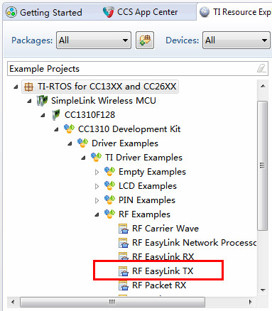
Yesterday, everything was fine. I can run and debug this project. But today, when I try to run and debug this project, I have the following problems:
Cortex_M3_0: GEL Output: Memory Map Initialization Complete.
Cortex_M3_0: GEL Output: Board Reset Complete.
Cortex_M3_0: Can't Run Target CPU: (Error -2134 @ 0x0) Unable to control device execution state. Reset the device, and retry the operation. If error persists, confirm configuration, power-cycle the board, and/or try more reliable JTAG settings (e.g. lower TCLK). (Emulation package 6.0.14.5)
Cortex_M3_0: JTAG Communication Error: (Error -1170 @ 0x0) Unable to access the DAP. Reset the device, and retry the operation. If error persists, confirm configuration, power-cycle the board, and/or try more reliable JTAG settings (e.g. lower TCLK). (Emulation package 6.0.14.5)
I can compile this project and I can load this project, but then I have the above problems.
Moreover, I use the "Test Connection" button to test connection, as shown below,

And there is no problem in every kind of test, which can been below.
[Start: Texas Instruments XDS100v3 USB Debug Probe]
Execute the command:
%ccs_base%/common/uscif/dbgjtag -f %boarddatafile% -rv -o -F inform,logfile=yes -S pathlength -S integrity
[Result]
-----[Print the board config pathname(s)]------------------------------------
C:\Users\YLW\AppData\Local\TEXASI~1\CCS\
ti\0\0\BrdDat\testBoard.dat
-----[Print the reset-command software log-file]-----------------------------
This utility has selected a 100- or 510-class product.
This utility will load the adapter 'jioserdesusbv3.dll'.
The library build date was 'Sep 4 2015'.
The library build time was '21:59:23'.
The library package version is '6.0.14.5'.
The library component version is '35.35.0.0'.
The controller does not use a programmable FPGA.
The controller has a version number of '4' (0x00000004).
The controller has an insertion length of '0' (0x00000000).
This utility will attempt to reset the controller.
This utility has successfully reset the controller.
-----[Print the reset-command hardware log-file]-----------------------------
The scan-path will be reset by toggling the JTAG TRST signal.
The controller is the FTDI FT2232 with USB interface.
The link from controller to target is direct (without cable).
The software is configured for FTDI FT2232 features.
The controller cannot monitor the value on the EMU[0] pin.
The controller cannot monitor the value on the EMU[1] pin.
The controller cannot control the timing on output pins.
The controller cannot control the timing on input pins.
The scan-path link-delay has been set to exactly '0' (0x0000).
-----[The log-file for the JTAG TCLK output generated from the PLL]----------
Test Size Coord MHz Flag Result Description
~~~~ ~~~~ ~~~~~~~ ~~~~~~~~ ~~~~ ~~~~~~~~~~~ ~~~~~~~~~~~~~~~~~~~
1 64 - 01 00 500.0kHz O good value measure path length
2 64 + 01 20 3.000MHz [O] good value apply explicit tclk
There is no hardware for measuring the JTAG TCLK frequency.
In the scan-path tests:
The test length was 2048 bits.
The JTAG IR length was 10 bits.
The JTAG DR length was 2 bits.
The IR/DR scan-path tests used 2 frequencies.
The IR/DR scan-path tests used 500.0kHz as the initial frequency.
The IR/DR scan-path tests used 3.000MHz as the highest frequency.
The IR/DR scan-path tests used 3.000MHz as the final frequency.
-----[Measure the source and frequency of the final JTAG TCLKR input]--------
There is no hardware for measuring the JTAG TCLK frequency.
-----[Perform the standard path-length test on the JTAG IR and DR]-----------
This path-length test uses blocks of 64 32-bit words.
The test for the JTAG IR instruction path-length succeeded.
The JTAG IR instruction path-length is 10 bits.
The test for the JTAG DR bypass path-length succeeded.
The JTAG DR bypass path-length is 2 bits.
-----[Perform the Integrity scan-test on the JTAG IR]------------------------
This test will use blocks of 64 32-bit words.
This test will be applied just once.
Do a test using 0xFFFFFFFF.
Scan tests: 1, skipped: 0, failed: 0
Do a test using 0x00000000.
Scan tests: 2, skipped: 0, failed: 0
Do a test using 0xFE03E0E2.
Scan tests: 3, skipped: 0, failed: 0
Do a test using 0x01FC1F1D.
Scan tests: 4, skipped: 0, failed: 0
Do a test using 0x5533CCAA.
Scan tests: 5, skipped: 0, failed: 0
Do a test using 0xAACC3355.
Scan tests: 6, skipped: 0, failed: 0
All of the values were scanned correctly.
The JTAG IR Integrity scan-test has succeeded.
-----[Perform the Integrity scan-test on the JTAG DR]------------------------
This test will use blocks of 64 32-bit words.
This test will be applied just once.
Do a test using 0xFFFFFFFF.
Scan tests: 1, skipped: 0, failed: 0
Do a test using 0x00000000.
Scan tests: 2, skipped: 0, failed: 0
Do a test using 0xFE03E0E2.
Scan tests: 3, skipped: 0, failed: 0
Do a test using 0x01FC1F1D.
Scan tests: 4, skipped: 0, failed: 0
Do a test using 0x5533CCAA.
Scan tests: 5, skipped: 0, failed: 0
Do a test using 0xAACC3355.
Scan tests: 6, skipped: 0, failed: 0
All of the values were scanned correctly.
The JTAG DR Integrity scan-test has succeeded.
[End: Texas Instruments XDS100v3 USB Debug Probe]
As you can see, every test has succeeded.
How to solve my problem? Thank you.
