This thread has been locked.

If you have a related question, please click the "Ask a related question" button in the top right corner. The newly created question will be automatically linked to this question.

problem with UART communications - ERROR _c_int00_noargs_noexit() at boot_special.c:103 0xC2FC (the entry point was reached)

Other Parts Discussed in Thread: MSP430G2553, ENERGIA, MSP-EXP430FR4133, MSP-FET

Hi, I'm very new to this, but I'm looking to get basic terminal output from a MSP430G2553 Launchpad. Everytime I run example code that involves the UART, I'm getting the following debug stop message:

_c_int00_noargs_noexit() at boot_special.c:103 0xC2FC (the entry point was reached)

I have no idea what this is. I did look around and found this message:

What is this function and why am I stuck in it?

https://e2e.ti.com/support/microcontrollers/msp430/f/166/p/407538/1445097

This looks like the same symptoms, but he references that some of his other code turned the interrupts off and he needed to turn them on. How do I do this? I just want my terminal to work.

PS the current test code is msp430g2xx3_ta_uart9600 from the MSP430 demo code

( http://www.ti.com/product/MSP430G2553/toolssoftware First line in software section )

Sys Specs: win 10 64-bit, CCS Version: 6.2.0.00050

  • I'm totally baffeled at this point.  I got another one of the MSP430G2553 launchpads, new out of the wrapper and ran the program.  Same problem.  Is the board erroring out because of a windows driver???  I can't believe every sample code is bad, yet, everything errors out at the same point.  Also I can't get serial communications with Energia.  This has been 4 days on what I consider a very basic problem.

    PS I ran the same Enegia code (Ascii table) on an Arduino an got immediate results.  no trouble shoot, it just works, the was it's supposed to.

  • Chris Cherry said:
    Everytime I run example code that involves the UART, I'm getting the following debug stop message:

    _c_int00_noargs_noexit() at boot_special.c:103 0xC2FC (the entry point was reached)

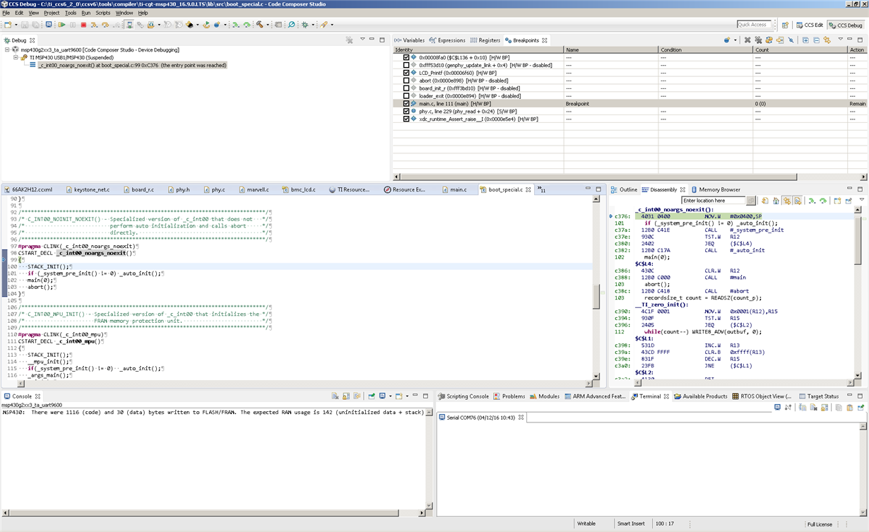
    Do you mean that when you start a debug session, that the debugger shows the program at the start of the _c_int00_noargs_noexit function? i.e. similar to the following screen-shot:

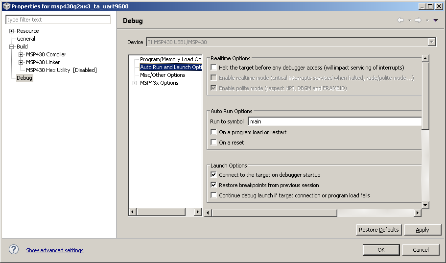
    If so, it probably means that the Debug "Auto Run Options" in the project properties are set to the following, which means when a debug session is started then the program is halted at the code entry point:

    See Auto Run and Launch Options for more information on these settings.

    The default for a new project should be that the "Run to symbol" is main and the "On a program load or restart" option is ticked, which when a debug session is started cause the program to be halted at the entry to main.

  • I setup the debug the same way, same execution, nothing changed.  

    its not just the halt,  I have continued the program and there is no serial communications thru the USB.  Looking around, this is a septicemic problem with this prototype board that TI doesn't want to address.  After 5 days of heavy internet searching with others having the same issue no real answers to this serial and TI directly telling me to go to the forum for answers. Tomorrow I'm returning these 2 boards and getting a chip that works, I have the 2 other launchpads with builtin LCD displays on the way.  As I continue with the project development I have serious doubt of the quality for support from TI that is needed for a startup.  Please keep in mind that I got a PIC processor to have serial communications on day one (technically on hour 1) and I got an Ardiuno board to have serial communications on hour one.  This is a crappy product and I'm hoping the other boards coming it have a better usb interface then this.  So fare I would not recommend this chip or TI to my employer.

    PS please do not respond unless you have a MSP430G2553.  It seams any other launchpad board doesn't have these issues.  TI Fix you board or driver!!! this is crap!!!! 

  • Chris Cherry said:
    its not just the halt,  I have continued the program and there is no serial communications thru the USB.

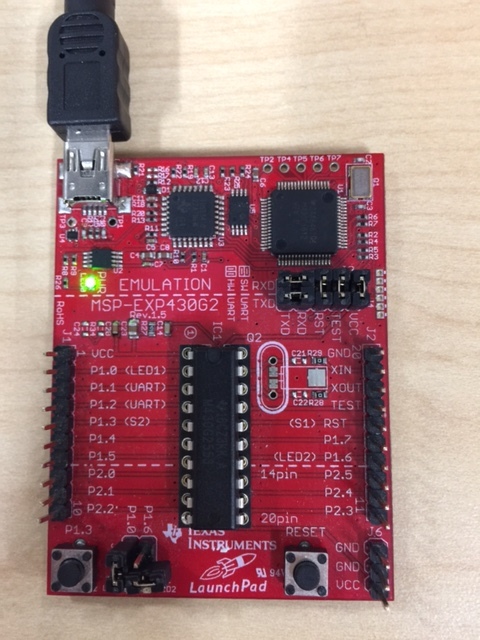
    The  msp430g2xx3_ta_uart9600 example uses a software UART, which means the the RXD and TXD jumpers on the MSP-EXP430G2 need to be the "SW UART" position to be able to get any UART output.

    Can you confirm how the jumpers are set?

  • My test procedure:
    - un plug the board
    - replug the board back in
    - re complite
    - download and run
    - un plug the board
    - change the jumpers
    - un plug the board
    - replug the board back in
    - re complite
    - download and run

    I also have tried the built in terminal set on serial and PuTTY. (PuTTY works like a charm with Arduino)
  • Hi Chris,

    I apologize for the trouble you're experiencing but I'm sure we can get you back on track. I have a few questions first:

    Have you made any changes to the default example msp430g2xx3_ta_uart9600?
    Also, is there a reason you are using the timerA uart example instead of the USCI uart example (msp430g2xx3uscia0_uart_01_9600.c)?
    Finally, could you try loading the default blinky example (msp430g2xx3_1.c) and let me know if you still experience any issues? This way we can try to narrow down whether its a hardware issue or software.

    Best regards,
    Caleb Overbay
  • Update:  Half success.  I recently purchased a MSP-EXP430FR4133 board.  This board, when installed, shows as 2 com ports.  In Windows 10 device manager they are listed as MSP Debug Interface (COM9) and MSP Application UART (COM8).  I was playing with this board and found that using Energia running the ASCIITable example, and commenting out any line that disables the watchdog timer (//WDTCTL = WDTPW + WDTHOLD; ) , that I could get serial comms on the  MSP Application UART connection.

    I also purchased a USB TTL that supports 3.3v.  On the MSP430G2553 I succfully got communications thru the TTL connection.    The half success is only a half since I had to use an external TTL to USB board. 

    So my questions are:

    For the MSP-EXP430G2 boards, why isn't the connection MSP430 Application UART (COM1) work?

    Where is the debug port?  

    Also why are the examples wrong when they state to disable the watchdog timer? 

  • Hi Chris, 

    Also why are the examples wrong when they state to disable the watchdog timer? 

    The behavior you're seeing isn't typical of the MSP-EXP430FR4133. By not disabling the WDT, a periodic PUC should be occurring. This would most likely cause the communications to fail, so I'm puzzled that it seems to be working when this is disabled. 

    Where is the debug port?

    The MSP-EXP430G2 should only show a UART port in the device manager. Also, the MSP-EXP430FR4133 should show both a UART and debug port. So it looks like things are operating correctly in that aspect. 

    For the MSP-EXP430G2 boards, why isn't the connection MSP430 Application UART (COM1) work?

    This is something we need to dig a little deeper into. Can you share how the jumpers are arranged on the board? Also, have you made any changes to the default example such as which pins the device is using for RXD and TXD?

    Finally, I still recommend using the USCI UART example over the TimerA UART example. It would be much simpler to debug and find out what is going wrong. 

    Best regards, 

    Caleb Overbay

  • Can you share how the jumpers are arranged on the board?

    >> Since I really don't understand the difference of the RX and TX jumpers in the vertical verses horizontal (I do understand what RX and TX are, just not the difference of software vs. hardware). I try every test in both of the configurations. Once in a while I would get garbage out (Right number of charaters, but unrecognizable, but not consistantly). I also have tried the internal terminal program in CCS 6.2 and PuTTy. I like putty better since I work with Linux all the time.

    Also the msp430g2xx3uscia0_uart_01_9600.c program worked with and without the watchdog timer commented out.
  • Hi Chris, 

    You can use any terminal application you like to communicate with the MSP430. It doesn't have to be the one inside of CCS. I personally use PuTTy myself. 

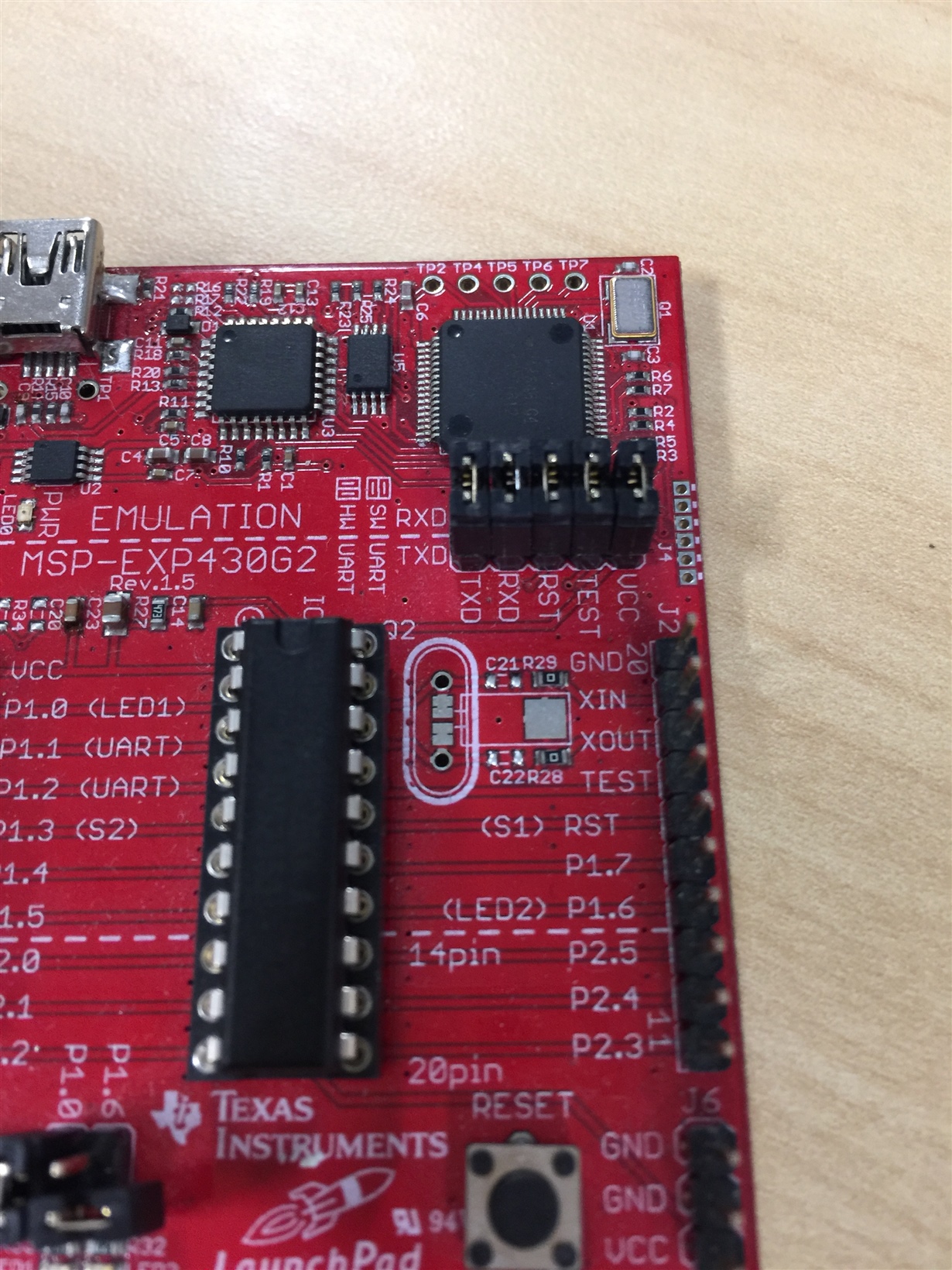
    The RX and TX pins are the UART receive and transmit pins receptively for the MSP430G2553 on the LaunchPad. For communication to a PC to be possible these need to be in the "vertical" position as shown in the below picture:

    There are only select pins that can be used as the RX and TX on this particular LaunchPad and MSP430G2553. This is P1.1 as the RX and P1.2 as the TX. These are typically used by default in the examples. 

    Typically, when you're receiving characters but they are unrecognizable it is a baud rate issue. Make sure that the terminal application is set to a baud rate of 9600. Also, the MSP-EXP430G2 launchpad has a maximum baud rate of 9600. This is a hardware limitation set by the ez-fet used on the board. If you try to exceed this through the back-channel UART, you will get unrecognizable characters. You can achieve higher baud rates by connecting directly through the pins and not going through the USB connection available on this launchpad.

     Finally, you mentioned the USCI example worked. Does this mean you are able to successfully communicate with the device via a terminal on your PC?

    Best regards, 
    Caleb Overbay

  • The stock program worked, but only with an external "usb to TTL" converter connected to P1.1 and P1.2 and the TX and RX jumpers removed.  

    After successful TTL test (I know the software on the MSP430 is good), I did the following

    Unplugged the board, removed the TTL board and placed the jumpers vertical, like the photo.  Plugged back in to usb cable.  No communications with PuTTY.  Hit the reset and tested again.  No luck.  

    PuTTY settings:

    Baud: 9600

    Data Bits: 8

    Stop Bits: 1

    Parity: None

    Flow Control: None

    Out of curiosity, Do you have one of these boards with you that successfully works with a windows 10 machine?  If so can you tell me the driver version you are using.  I'm using 1.5.0.0.  Also is there a way to check the version number of the FET program?

    Thanks

  • Hi Chris, 

    I apologize for not explaining myself well enough in my previous post. Which revision of the MSP-EXP430G2 are you working with?

    On Rev 1.5 there are two possible configurations for the UART Rx and Tx jumpers:

    When using the SW UART example that utilizes Timer_A (msp430g2xx3_ta_uart9600.c) the jumpers should be in the vertical position:

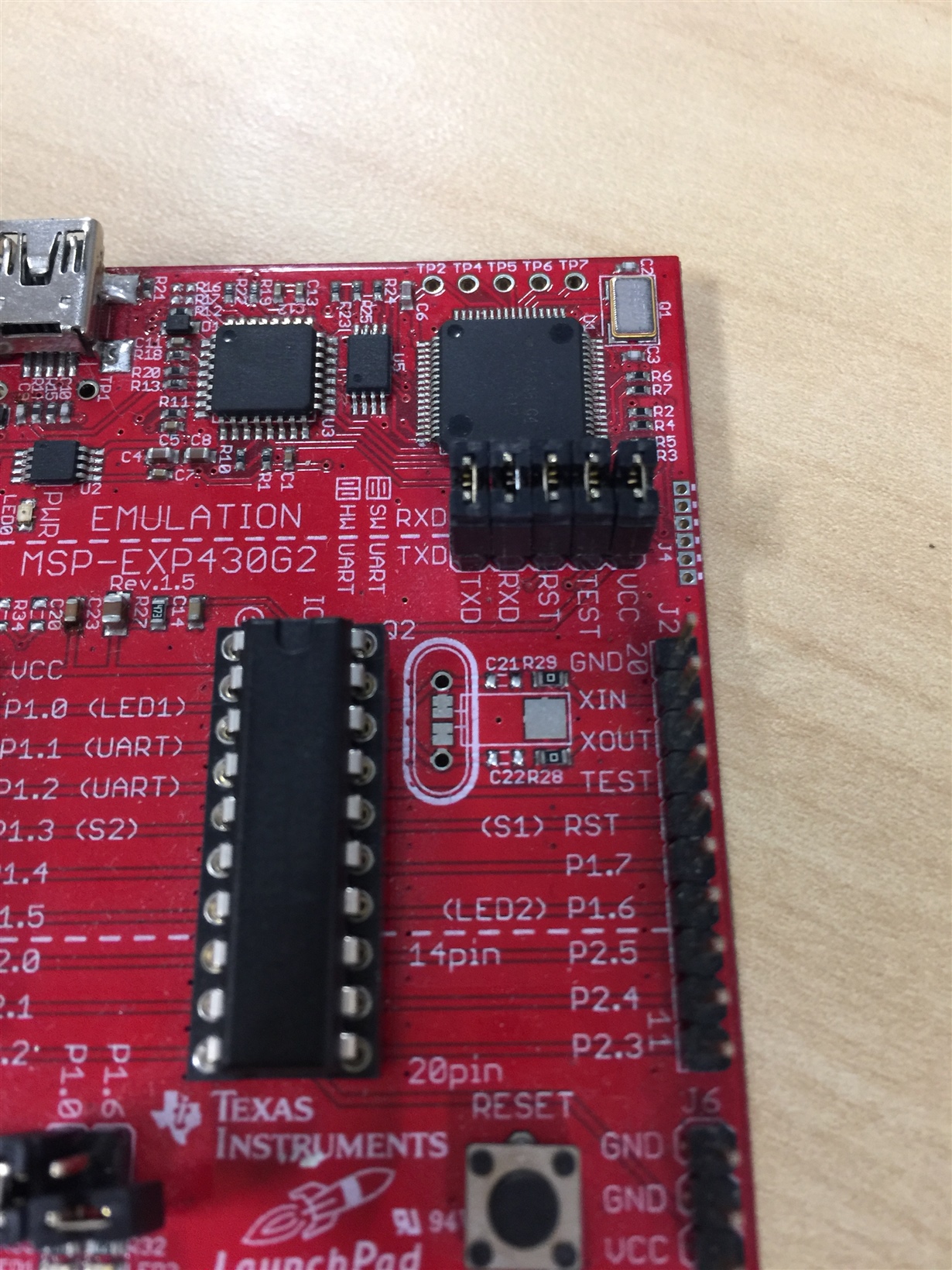
    When using the HW UART example that utilizes the USI module (msp430g2xx3_uscia0_uart_01_9600.c) the jumpers need to be configured horizontally:

    When this LaunchPad was first designed, there was no hardware UART implementation and the jumpers connected to Timer_A pins. With the introduction of the USCI module on the G2xx devices, Rev 1.5 "fixed" this by adding the ability to connect the USCI pins by turning the jumpers horizontally. 

    Unfortunately, I do not have a windows 10 machine to test this on. However, the driver version you've listed is the same one I have. Also, are you asking about how to find the version number of the MSP-FET programmer? 

    Best regards, 
    Caleb Overbay

  • >>I know the MSP-EXP430G2 is revision 1.5.

    >>So should the jumpers be vertical or horizontal?  (every test I do try both vertical and horizontal, see testing procedure above)

    Unfortunately, I do not have a windows 10 machine to test this on. However, the driver version you've listed is the same one I have.

    >> So are you running win 7, 8 or XP?  XP is a totally different beast and not even close to Win 7, 8 or 10.

    Also, are you asking about how to find the version number of the MSP-FET programmer? 

    >> when ever I get a new board (I'm up to 4 of these) as soon as I try to program it using CCS, it has to update some sort of firmware.  I believe it's the MSP-FET.  how do I find out what version I'm on?

    >> The bottom line.  The actual MSP430G2553 chip is doing what it's supposed to do (Proven by the TTL board communicating with it).  The MSP-FET or windows driver is failing to perform it's function.  So with this in mind, i'm looking at anything that's different from a working setup (Yours) vs. my setup.  Also please don't just say try horizontal vs vertical jumper settings.  I try both until I get something to work.  Please focus on FET and win drivers.  The problem is somewhere in there.  In the last post there was nothing that I hadn't already tried.


  • Hi Chris, 

    >>So should the jumpers be vertical or horizontal?  (every test I do try both vertical and horizontal, see testing procedure above)

    This depends on which program you are using:

    • TimerA UART = Vertical
    • USCI UART = Horizontal

    The MSP-EXP430G2 has been tested with windows 10 and proven to work, so don't believe it's an issue with drivers or windows versions.


    After doing some digging, your symptoms seem to be closer to this E2E thread: MSP430 Launchpad Serial on Windows with USB3

    Are you trying to communicate over USB3? As seen in the post, there is a note in Section 4.3 of the MSP Debuggers guide  stating that eZ430 tools like MSP-EXP430G2 are not supported on USB 3.0 ports. There is no such note for eZ-FET based tools, like any of the other newer launchpads MSP-EXP430FR4133 MSP-EXP430FR5969 MSP-EXP430F5529LP MSP-EXP430FR6989

    Best regards, 
    Caleb Overbay

  • I was. Tried with USB 2.0 ports. Still no Luck. I'm going to close this, because I can use my TTL converter for what I need. I will say that I would not recommenced this board to anyone. Start with anything with the eZ-FETs