Tool/software: Code Composer Studio
Hello, I would appreciate a solution to the following problem:
I have just loaded and updated CCS 7 (Version: 7.1.0.00016 ) on my PC#2 (Win 7), and trying to run the program inserted in this post that is running on another PC#1 (Win 7) of mine running CCS 6.
I do not currently have access to PC#1 as I am currently remote.
I added the main.c file directly into a new Project from the functioning version of this code on PC#1.
When I build the new Project on PC#2 I am receiving the following two errors:
1. Error #10234-D: unresolved symbols
2. Error #10010: errors encountered during linking
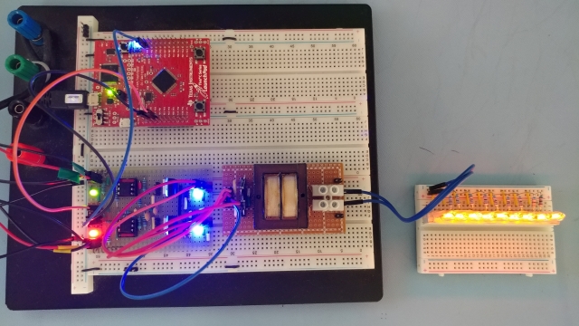
BTW, "blinky" loads and runs on my LaunchPad (TM4C123GXL).
Thanks!
Error descriptions:

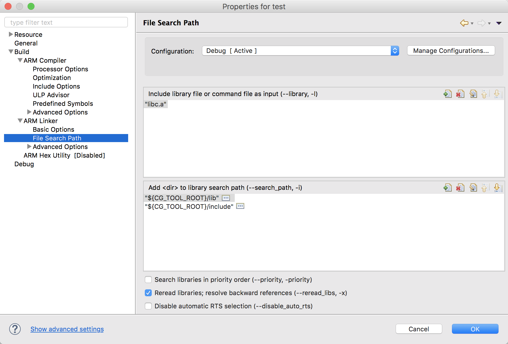
Properties:

Code
The API's are not highlighting. Possibly I am not referencing the API source library correctly, or at all, or I am using the incorrect compiler, or?
Also, I have removed reference ROM_ to the API's, which was functioning on my other PC (Win 7) running CCS 6.
* Optocoupler driver (4N25) for N-Channel MOSFET (IRF630) power supply.
 * See schematic: N-channel MOSFET with optocoupler

 * This code uses PWM Module 1 Generator 0 and Generator 3

 * PWM Module 1 Generator 0: M1PWM0, GPIO pin PD0. PWMGenConfigure using PWM_GEN_MODE_DOWN
 	In count down mode, it will count from a value down to zero,
	and then reset to the preset value.
	This will produce left-aligned PWM signals
	(that is the rising edge of the two PWM signals
	produced by the generator will occur at the same time).

 * PWM Module 1 Generator 3: M1PWM6, GPIO pin PF2. PWMGenConfigure using PWM_GEN_MODE_UP_DOWN
 	 In count up/down mode, it will count up from zero to the preset value, count back down to zero,
 	 and then repeat the process. This will produce center-aligned PWM signals
 	 (that is, the middle of the high/low period of the PWM
 	 signals produced by the generator will occur at the same time).*/


#include <stdint.h>
#include <stdbool.h>
#include "inc/hw_memmap.h"
#include "inc/hw_types.h"
#include "driverlib/sysctl.h"
#include "driverlib/gpio.h"
#include "driverlib/debug.h"
#include "driverlib/pwm.h"
#include "driverlib/pin_map.h"
#include "inc/hw_gpio.h"  // Not required for this program
//#include "driverlib/rom.h"

int main( void )
{


	// Set-up System Clock (SYSCLK) and PWM Clock (PWMCLK)

    SysCtlClockSet( SYSCTL_SYSDIV_10 | SYSCTL_USE_PLL | SYSCTL_OSC_MAIN | SYSCTL_XTAL_16MHZ ); // SYSCLK set to 20 MHz (referred to as "ticks")
    											// TM4C123x_ROM USER’S GUIDE page 199/348
												// TM4C123GH6PM RevE DataSheet, Register 8: Run-Mode Clock Configuration (RCC), offset 0x060
    												// SYSCTL_OSC_MAIN = OSCSRC (Oscillator Source), MOSC (Main oscillator), page 257 / 1409
    												// SYSCTL_XTAL_16MHZ = XTAL (Crystal Value), page 256/1409
    												// SYSCTL_SYSDIV_10 = SYSDIV (System Clock Divisor), page 254/1409
    												// SYSCTL_USE_PLL = USEPWMDIV (Enable PWM Clock Divisor), page 255/1409

    // Set-up PWM Clock (PWMCLK)

    SysCtlPWMClockSet( SYSCTL_PWMDIV_64 ); // Sets the PWM clock by dividing the 20.0 MHz (ticks) SYSCLK by 64 = PWM clock 312.5 KHz [312,500 Hz] (PWMCLK)
    											// TM4C123x_ROM USER’S GUIDE page 217/348
    											// TM4C123GH6PM RevE DataSheet, Register 8: Run-Mode Clock Configuration (RCC), offset 0x060
    											// SYSCTL_PWMDIV_64 = PWMDIV, page 255/1409

    // Enable PWM module 1, Generator 0 to output on GPIO Port D, pin 0, and Generator 3 to output on GPIO Port F, pin 2

    SysCtlPeripheralEnable( SYSCTL_PERIPH_PWM1 ); // Enable the PWM peripheral PWM module 1

    SysCtlPeripheralEnable( SYSCTL_PERIPH_GPIOD ); // Enable GPIO: Port D

    SysCtlPeripheralEnable( SYSCTL_PERIPH_GPIOF ); // Enable GPIO: Port F


/*-----Configure PWM module 1, Generator 0, PWM 1 to output a defined frequency and pulse duty cycle on GPIO GPIO Port D, Pin PD0 M1PWM0 */


    GPIOPinTypePWM( GPIO_PORTD_BASE, GPIO_PIN_0 ); // Configures Port D, Pin 0 for use by the PWM peripheral.
    												//The program loads but will not run on the TM4C123G_LaunchPad when it is a ROM_ API
    												// The program loads and runs on the TM4C123G_LaunchPad when it is a 2.1.3.156 Driver Library API


    GPIOPinConfigure( GPIO_PD0_M1PWM0 ); // Configures the alternate function of Port D, Pin 0 to PWM output
    										 // TM4C123GH6PM Microcontroller Data Sheet-SPMS376E, 23.4 GPIO Pins and Alternate Functions, p1351


    PWMGenConfigure( PWM1_BASE, PWM_GEN_0, PWM_GEN_MODE_DOWN ); // Configures a PWM Module 1, Generator 0. In MODE_DOWN, counts from the PWM generator's Period (load) down to zero,
    																// and then reset to the preset PWM generator's Period (load) value.
    																// Tiva C Series TM4C123x ROM USER’S GUIDE, PWM, 15.2.1.5 ROM_PWMGenConfigure, page 157.
    																// TM4C123GH6PM Microcontroller Data Sheet-SPMS376E, 20.3.2 PWM Timer, p1234 & Figure 20-3. PWM Count-Down Mode, p1235

    PWMGenPeriodSet( PWM1_BASE, PWM_GEN_0, 5208 );  // Sets the PWM Generator 0's Period (load) value. This is the frequency of the square wave.
    													// The Period (load) value is defined as the number of PWM clock ticks between zero pulse signals on the generator block.
    													// PWMCLK frequency [ticks per second (Hz)] = 62,500 ticks per second
    													// PWM Period = (1/f) =  0.0000032 Seconds per tick
    													// Desired frequency [f] = number of Hz
    													// Desired period = (1/f) = Seconds per period
    													// Ticks per desired period = Seconds per period / Seconds per tick
    													// 60 Hz = 5208 ticks

    //ROM_PWMDeadBandEnable(PWM1_BASE, PWM_GEN_0, 1000, 1000);  // Enable the dead-band generation on the PWM0 output signal as a percentage of the PWMGenPeriodSet ticks
    													// % of PWMGenPeriodSet ticks =

    PWMPulseWidthSet( PWM1_BASE, PWM_OUT_0,  ( PWMGenPeriodGet(PWM1_BASE, PWM_GEN_0) / 4) ); // Sets the PWM Generator 0 pulse width output by using PWMGenPeriodGet to get the period previously set.
    																							 // Set Duty Cycle: In this case PWM generator's period is divided the by 10 to get 10% duty cycle.


    PWMOutputState( PWM1_BASE, PWM_OUT_0_BIT, true ); // Enables the output of PWM Module 1, Generator 0


    PWMGenEnable( PWM1_BASE, PWM_GEN_0 );  // Enables the timer/counter for a PWM Module 1, Generator 0

    GPIOPadConfigSet(GPIO_PORTD_BASE, GPIO_PIN_0, GPIO_STRENGTH_8MA, GPIO_PIN_TYPE_STD);    // Enable GPIO Port D Pad and Pins 0 for 8 MA output


/*----- Configure PWM module 1, Generator 3, PWM 1 to output a defined frequency and pulse duty cycle on GPIO Port F, Pin PF2 M1PWM6 --------*/


    GPIOPinTypePWM( GPIO_PORTF_BASE, GPIO_PIN_2 ); // Configures Port F, Pin 2 for use by the PWM peripheral
    												//The program loads but will not run on the TM4C123G_LaunchPad when it is a ROM_ API
    												// The program loads and runs on the TM4C123G_LaunchPad when it is a 2.1.3.156 Driver Library API


    GPIOPinConfigure( GPIO_PF2_M1PWM6 ); // Configures the alternate function of Port F, Pin 0 to PWM output
    										 // TM4C123GH6PM Microcontroller Data Sheet-SPMS376E, 23.4 GPIO Pins and Alternate Functions, p1351

    PWMGenConfigure( PWM1_BASE, PWM_GEN_3, PWM_GEN_MODE_UP_DOWN ); // Configures a PWM Module 1, Generator 2. In MODE_UP_DOWN, counts from the PWM generator's Period (load) down to zero,
    																	/*In count up/down mode, it will count up from zero to the preset value,
    																	count back down to zero, and then repeat the process.
    																	This will produce center-aligned PWM signals
    																	(that is, the middle of the high/low period of the PWM
    																	signals produced by the generator will occur at the same time).*/
    																// Tiva C Series TM4C123x ROM USER’S GUIDE, PWM, 15.2.1.5 ROM_PWMGenConfigure, page 157
    																// TM4C123GH6PM Microcontroller Data Sheet-SPMS376E, 20.3.2 PWM Timer, p1234 & Figure 20-4. PWM Count-Up/Down Mode, p1235


    PWMGenPeriodSet( PWM1_BASE, PWM_GEN_3, 5208 );  // Sets the PWM Generator 0's Period (load) value. This is the frequency of the square wave.
    													// The Period (load) value is defined as the number of PWM clock ticks between zero pulse signals on the generator block.
    													// PWMCLK frequency [ticks per second (Hz)] = 62,500 ticks per second
    													// PWM Period = (1/f) =  0.0000032 Seconds per tick
    													// Desired frequency [f] = number of Hz
    													// Desired period = (1/f) = Seconds per period
    													// Ticks per desired period = Seconds per period / Seconds per tick
    													// 60 Hz = 5208 ticks

    PWMDeadBandEnable(PWM1_BASE, PWM_GEN_3, 200, 200);  // Enable the dead-band generation on the PWM0 output signal as a percentage of the PWMGenPeriodSet ticks
    													// % of PWMGenPeriodSet ticks =

    PWMPulseWidthSet( PWM1_BASE, PWM_OUT_6,  ( PWMGenPeriodGet(PWM1_BASE, PWM_GEN_3) / 4 ) ); // Sets the PWM Generator 0 pulse width output (Duty Cycle) by using PWMGenPeriodGet to get the period previously set.
    																							 // In this case PWM generator's period is divided the by 10 to get 10% duty cycle.

 //ROM_PWMOutputInvert(PWM1_BASE, PWM_OUT_0_BIT, true);   // Inverts the output of PWM Module 1, Generator 0, Bit 1
 //(This function is not needed as a PWM's Generators two outputs are mutually inverted)

    PWMOutputState( PWM1_BASE, PWM_OUT_6_BIT, true ); // Enables the output of PWM Module 1, Generator 2, PWM 4

    PWMGenEnable( PWM1_BASE, PWM_GEN_3 );  // Enables the timer/counter for a PWM Module 1, Generator 0

    GPIOPadConfigSet(GPIO_PORTF_BASE, GPIO_PIN_2, GPIO_STRENGTH_8MA, GPIO_PIN_TYPE_STD);    // Enable GPIO Port F Pad and Pin 0 for 8 MA output


    while( 1 ) {
        ;
    }
}