This thread has been locked.

If you have a related question, please click the "Ask a related question" button in the top right corner. The newly created question will be automatically linked to this question.

Inline hex code for 20-bit adress jump

Other Parts Discussed in Thread: MSP430F5359

Hello,

We are currently working on a main memory bootloader that is based on the MSPBoot project, this bootloader uses a proxy table that hat uses a BRA instrunction to a ISR.

The orgional bootloader uses a 16-bit BRA instruction to jump to a given ISR, this instruction is if we are correct represented by the hex value 0x4030.

 Table proxy table entrys are then e.g.:

0x4030, (uint16_t) NameOfISRRoutine1

0x4030, (uint16_t) NameOfISRRoutine2

etc

Because of our code size (it extens above the first 64kb) we need to make 20-bit jumps, can someone tell us where w can find the hex value for a 20-bit address jump? Or what the hex value of a 20-bit jump (BRA instruction) is? Our target is the MSP430F5359, and we use code composer version 5.5.

Many thanks in advance.

PS we did't know if this is the right forum section, if not please forgive us.

  • From looking at the MSP430x5xx and MSP430x6xx Family User's Guide SLAU208N:

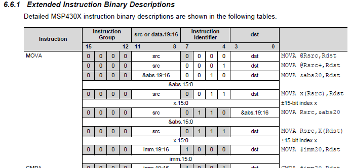
    1) BRA dst is emulated by MOVA dst,PC

    2) The encoding for MOVA with a 20 bit immediate address is given in the following table:

    Since the MOVA #imm20,PC has the most significant 4 bits of the immediate value encoded in one nibble of a 16-bit word I couldn't get the compiler to accept an expression in a uint16_t constant array which shifted part of a function address - since the compiler reported "error #28: expression must have a constant value" when attempted the following to encode the following:

    const uint16_t jump_table[] =
    {
    	0x0080 | ((((uint32_t) NameOfISRRoutine1) >> 8) & 0x0f00), (uint32_t) NameOfISRRoutine1 & 0xffff,
    	0x0080 | ((((uint32_t) NameOfISRRoutine2) >> 8) & 0x0f00), (uint32_t) NameOfISRRoutine2 & 0xffff,
    };
    

    Therefore, suggest you use an assembler source file to create the BRA proxy table with the 20 bit function addresses.

  • Hi Chester,

    Thank you for your reply! After some searching i found a simalir post:

    Here someone has sugested the same suggestion (with the same compiler error), but also another suggestion (a small diffrence?):

    (0x0080 | 0x01), (uint16_t)(uint32_t)Isr,

    Could this also work?  If we add or proxy table entrys this way? Our assembly knowledge is not that great, so if we could handle this in c that would be our prefference.

    Thank you four your response.

  • Roy Stegers said:

    Here someone has sugested the same suggestion (with the same compiler error), but also another suggestion (a small diffrence?):

    (0x0080 | 0x01), (uint16_t)(uint32_t)Isr,

    Could this also work?

    As noted in the other thread, the limitation of that code is that the most significant 4 address bits are hard-coded in the ProxyVectorTable which means the linker command file has to constrain the memory address range of the functions referenced by the ProxyVectorTable to match.

    I found that it is possible to use inline assembler in a C source file to encode a BRA to a 20-bit instruction , creating a look-up table. The following example shows this (with the ProxyVectorTable array placed in the .APP_PROXY_VECTORS section as per the MSPBoot example in the other thread):

    #include <msp430.h>
    #include <stdint.h>
    
    void NameOfISRRoutine1 (void)
    {
    
    }
    
    void NameOfISRRoutine2 (void)
    {
    
    }
    
    __asm (" .sect .APP_PROXY_VECTORS");
    __asm (" .global ProxyVectorTable");
    __asm ("ProxyVectorTable:");
    __asm (" BRA #NameOfISRRoutine1;");
    __asm (" BRA #NameOfISRRoutine2;");
    
    extern const uint16_t ProxyVectorTable[];
    
    /*
     * main.c
     */
    int main(void) {
        WDTCTL = WDTPW | WDTHOLD;	// Stop watchdog timer
    	
    	return ProxyVectorTable[0];
    }
    

    I haven't tried this in MSPBoot, but I did download the above program into flash and check in the debugger that the ProxyVectorTable did encode a 20-bit address for the target function as expected.

  • 
    

    Hi Chester,

    Thank you that works! Our button interrupts are working correctly!

    Below is our table (for anyone who faces the same issue), its for the MSP430F5359 MCU, we hope it is correct:

    __asm (" .sect .APP_PROXY_VECTORS");
    __asm (" .global ProxyVectorTable");
    __asm ("ProxyVectorTable:");
    __asm (" BRA #Dummy_Isr;");	 // APP_PROXY_VECTOR(0) USCI_B2, TODO is UNUSED
    __asm (" BRA #USCI_B2_ISR;");	 // APP_PROXY_VECTOR(0) USCI_B2, TODO is UNUSED
    __asm (" BRA #Dummy_Isr;");	 // APP_PROXY_VECTOR(1) USCI_A2  TODO is USCI_B2
    __asm (" BRA #Dummy_Isr;");	 // APP_PROXY_VECTOR(2) PORT P4
    __asm (" BRA #Dummy_Isr;");	 // APP_PROXY_VECTOR(3) PORT P3
    __asm (" BRA #Dummy_Isr;");	 // APP_PROXY_VECTOR(4) TIMER A2
    __asm (" BRA #Dummy_Isr;");	 // APP_PROXY_VECTOR(5) TIMER A2
    __asm (" BRA #Dummy_Isr;");  // APP_PROXY_VECTOR(6) DAC12_A
    __asm (" BRA #Dummy_Isr;");	 // APP_PROXY_VECTOR(7) RTC_B
    __asm (" BRA #Dummy_Isr;");  // APP_PROXY_VECTOR(8) LCD_B
    __asm (" BRA #Dummy_Isr2;"); // APP_PROXY_VECTOR(9) PORT P2
    __asm (" BRA #USCI_B1_ISR;");  // APP_PROXY_VECTOR(10) USCI_B1
    __asm (" BRA #Dummy_Isr;");  // APP_PROXY_VECTOR(11) USCI_A1
    __asm (" BRA #Dummy_Isr2;"); // APP_PROXY_VECTOR(12) PORT P1
    __asm (" BRA #TIMER_INTERRUPT;");  // APP_PROXY_VECTOR(13) TIMER A1
    __asm (" BRA #TIMER_INTERRUPT;");  // APP_PROXY_VECTOR(14) TIMER A1
    __asm (" BRA #Dummy_Isr;");   // APP_PROXY_VECTOR(15) DMA
    __asm (" BRA #Dummy_Isr;");   // APP_PROXY_VECTOR(16) LDO
    __asm (" BRA #Timer_A0;");    // APP_PROXY_VECTOR(17) USB
    __asm (" BRA #Timer_A0;");    // APP_PROXY_VECTOR(18) TIMER A0
    __asm (" BRA #Dummy_Isr;");   // APP_PROXY_VECTOR(19) TIMER A0
    __asm (" BRA #Dummy_Isr;");   // APP_PROXY_VECTOR(20) ADC12_A
    __asm (" BRA #USCI_B0_ISR;");   // APP_PROXY_VECTOR(21) USCI_B0
    __asm (" BRA #Dummy_Isr;");   // APP_PROXY_VECTOR(21) USCI_A0
    __asm (" BRA #Dummy_Isr;");   // APP_PROXY_VECTOR(21) WDT
    __asm (" BRA #Dummy_Isr;");   // APP_PROXY_VECTOR(21) TIMER TB0
    __asm (" BRA #Dummy_Isr;");   // APP_PROXY_VECTOR(21) TIMER TB0
    __asm (" BRA #Dummy_Isr;");   // APP_PROXY_VECTOR(21) COMP_B
    __asm (" BRA #Dummy_Isr;");   // APP_PROXY_VECTOR(21) USER_NMI

    We also placed the actual application code above 0x10000 by adjusting the linkerfile and placing .text in flash2. The .cinit, .const and .init are still in the lower memmory. Not shure that we need to put the .text_isr also in the highter memory? Is this nessicary? Our proxy table is till in the lower memory, does this need to be in the higher memory aswel?

    The timer interrupst seem als o to work, we only have one last problem that is with our I2C device, it seems we can not communictatie with them anymore.

    One of the device is a led chip and the interrupt ISR uses pointers to move data to the chip, what could be the reason that these interrupts do not work any more? As code model we use the large model.

    Below is our vector:

    //#pragma vector = USCI_B1_VECTOR
    __interrupt void USCI_B1_ISR(void)
    {
    	ActivateBuzzer(50, 250);
      switch(__even_in_range(UCB1IV,12))
      {
    	  case  0: break;                           // Vector  0: No interrupts
    	  case  2: break;                           // Vector  2: ALIFG
    	  case  4:
    	  	  {
    			  __bic_SR_register_on_exit(LPM0_bits + GIE); // Exit LPM0
    			  break;
    	  	  }// Vector  4: NACKIFG
    	  case  6: break;                           // Vector  6: STTIFG
    	  case  8: break;                           // Vector  8: STPIFG
    	  case 10: break;                           // Vector 10: RXIFG
    	  case 12:
    		  if(!bytesLeftToSent) {
    			  UCB1CTL1 |= UCTXSTP;                  // I2C stop condition// Vector 12: TXIFG
    			  __bic_SR_register_on_exit(LPM0_bits); // Exit LPM0
    		  }
    		  else {
    			  UCB1TXBUF = *dataToSend++;               // Load TX buffer
    			  bytesLeftToSent--;                          // Decrement TX byte counter
    		  }
    	  default: break;
      }
    }

    Once again thank you for your help!

  • Roy Stegers said:
    Not shure that we need to put the .text_isr also in the highter memory?

    The .text:_isr needs to be in the lower 64K of flash, as the interrupt vectors are only 16 bits.
    Roy Stegers said:
    Our proxy table is till in the lower memory, does this need to be in the higher memory aswel?
    The Proxy Table is referenced by the Interrupt Vectors and so the Proxy Table needs to reside in the lower memory.
    Roy Stegers said:
    One of the device is a led chip and the interrupt ISR uses pointers to move data to the chip, what could be the reason that these interrupts do not work any more? As code model we use the large model.
    What does dataToSend point to?

    i.e. is it pointing to data in ram (which therefore must be in lower memory) or is it pointing to constant data in flash (which may be in lower or upper memory)?

  • Hi Chester,

    Thank you for your quick response, mostly the LED chip handles const values, but it also handles some dynamic values. So we think .const need also to be in the lower memory, since it handles const values but also values in the RAM? This is actually also the case of some UART, and I2C devices on our design. Is there a way no make sure that the actual all the ISR functions are always in the lower memory? This way all the routines can have access to the RAM and const values.

    Or is this already done in the linker file by: .text_isr | FLASH? Does this forces all ISR's in the lower memory?


    And can we still use the table we made with the inline assembly functions? Or de we need to use the proxy table mentioned that is used in MSPBoot, since all the ISR's are in the lower memory (if this is possible?).

    Could there be another reason why the I2C does not seem to work? We also have added a buzzer beep the hear if the I2C ISR is even called, but it does not seem like it, we do not hear the beep, so we think that the ISR is not called.

    Once again thank you for your reply!

  • Roy Stegers said:
    Thank you for your quick response, mostly the LED chip handles const values, but it also handles some dynamic values. So we think .const need also to be in the lower memory, since it handles const values but also values in the RAM?

    What is the Data Model set to?

    If the Data Model is set to either "restricted" or "large" data pointers are 20-bits, which should allow data either in RAM or constant data in lower-memory or upper-memory to be accessed.

  • Hi Chester,

    The code and data model of both the bootloader and application project are set to large. We also checked the use large date model under advanced runtime options. Could this be the problem?

    Some more information, the initialisation of the I2C is as followes:

    	UCB0CTL1 |= UCSWRST;                      // Enable SW reset
    	UCB0CTL0 = UCMST + UCMODE_3 + UCSYNC;     // I2C Master, synchronous mode
    	UCB0CTL1 = UCSSEL_2 + UCSWRST;            // Use SMCLK, keep SW reset
    	UCB0BR0 = 12;                             // fSCL = SMCLK/12 = ~100kHz
    	UCB0BR1 = 0;
    	UCB0I2CSA = address;                         // Slave Address is 048h
    	UCB0CTL1 &= ~UCSWRST;                     // Clear SW reset, resume operation
    	UCB0IE |=  UCTXIE;                         // Enable TX interrupt
    
    	I2CPORT1 |= SDA1 + SCL1;
    

    And the the interface of I2C send function is:

    void SendI2C(const unsigned char Data[], unsigned char I2CPort, int TimeOutValue)

    When we call the I2C function the button interrupts and buzzer life beat, (that goes of every second) stop working, the seems to "hang".

    Thank you for your reply again!

  • The ProxyVectorTable in your previous post doesn't look correct for the MSP430F5359 device. i.e. the table starts with two entries which are commented as "APP_PROXY_VECTOR(0) USCI_B2", which would then cause the following interrupt vectors to be offset.

    Suggest you re-check that the ProxyVectorTable has defined the interrupts vectors in the correct order for your device.

    With the existing mis-behaving code you could also set a breakpoint on the Dummy_Isr. If the breakpoint is hit on Dummy_Isr it is a sign that the ProxyVectorTable is incorrect.

  • Hi Chester,

    Thank you again for your reply, we will check the table. Just to be sure you mean the table with the inline assembly functions right?

    The comment is indeed wrong, the first entry is for the unused space,  the bootloader table has as first entry UNUSED, this is a two byte value to mark the unused memory space. So e added an extra entry in the proxy table but is this needed?

    below is the bootloader table (the hex addresses in the comments are wrong):

    #       pragma DATA_SECTION(Vector_Table, ".BOOT_VECTOR_TABLE")
    #       pragma RETAIN(Vector_Table)
    const uint16_t Vector_Table[] =
    #   endif
    {
    	UNUSED,                                     // FFD0 = Reserved
    	APP_PROXY_VECTOR(0),                        // FFD2 = USCI_B2
    	APP_PROXY_VECTOR(1),                        // FFD4 = USCI_A2
    	APP_PROXY_VECTOR(2),                        // FFD6 = PORT P4
    	APP_PROXY_VECTOR(3),                        // FFD8 = PORT P3
    	APP_PROXY_VECTOR(4),                        // FFDA = TIMER TA2
    	APP_PROXY_VECTOR(5),                        // FFDC = TIMER TA2
    	APP_PROXY_VECTOR(6),                        // FFDE = DAC12_A
    	APP_PROXY_VECTOR(7),                        // FFE0 = RTC_B
    	APP_PROXY_VECTOR(8),                        // FFE2 = LCD
        APP_PROXY_VECTOR(9),                        // FFE4 = PORT P2
        APP_PROXY_VECTOR(10),			            // FFE6 = USCI_B1
        APP_PROXY_VECTOR(11),                       // FFE8 = USCI_A1
        APP_PROXY_VECTOR(12),                       // FFEA = PORT P1
        APP_PROXY_VECTOR(13),                       // FFEC = TIMER_A1
        APP_PROXY_VECTOR(14),                       // FFEE = TIMER_A1
        APP_PROXY_VECTOR(15),                       // FFF0 = DMA
        APP_PROXY_VECTOR(16),                       // FFF2 = LDO
        APP_PROXY_VECTOR(17),                       // FFF4 = USB
        APP_PROXY_VECTOR(18),                       // FFF6 = TIMER TA0
        APP_PROXY_VECTOR(19),                       // FFF8 = TIMER TA0
        APP_PROXY_VECTOR(20),                       // FFFA = ADC12_A
        APP_PROXY_VECTOR(21),                       // FFFC = UCSI_B0
        APP_PROXY_VECTOR(22),                       // FFFC = USCI_A0
        APP_PROXY_VECTOR(23),                       // FFFC = WDT
        APP_PROXY_VECTOR(24),                       // FFFC = TIMER TB0
        APP_PROXY_VECTOR(25),                       // FFFC = TIMER TB0
        APP_PROXY_VECTOR(26),                       // FFFC = COMP_B
        APP_PROXY_VECTOR(27),                       // FFFC = USER NMI
        APP_PROXY_VECTOR(28),                       // FFFC = SYSTEM NMI
    };
    

    UNUSED is defined as: 

    #define UNUSED                  (0x3FFF)     

    Should this be also a four byte value instead of a two byte value? Or can we remove it all together?

    APP_PROXY_VECTOR is defined as:

    #define APP_PROXY_VECTOR(x)     ((uint16_t)&_App_Proxy_Vector_Start[x*2])

    This is fine we think because the proxy table is also in the lower memory so can contain 16 bit addresses? Or should this be also 20 bit addrsses (for the BRA?)

    Each BRA entry in te proxy table is intotal four bytes right? So __asm (" BRA #Dummy_Isr;");   // APP_PROXY_VECTOR(21)  for instance is four bytes in size?

    We think that once we get the allignment right it should work!

    Thank you again for your effort!

  • Roy Stegers said:
    The comment is indeed wrong, the first entry is for the unused space,  the bootloader table has as first entry UNUSED, this is a two byte value to mark the unused memory space. So e added an extra entry in the proxy table but is this needed?

    While there is a reserved entry in the Vector_Table, the APP_PROXY_VECTOR macro only references the ProxyVectorTable indices 0..28 and therefore there shouldn't be the reserved entry at the start of the ProxyVectorTable.

    If you look at the MSP430Boot MSPBoot_1_01_00_00\Target\FR5739_I2C\Src\MSPBoot\AppMgr\TI_MSPBoot_VecRed_G2x52.c the Vector_Table does contain some UNSED entries:

    #   ifdef __IAR_SYSTEMS_ICC__
    #       pragma location="BOOT_VECTOR_TABLE"
    __root const uint16_t Vector_Table[] =
    #   elif defined (__TI_COMPILER_VERSION__)
    #       pragma DATA_SECTION(Vector_Table, ".BOOT_VECTOR_TABLE")
    #       pragma RETAIN(Vector_Table)
    const uint16_t Vector_Table[] =
    #   endif
    {
    
        UNUSED,                                     // FFE0 = unused
        UNUSED,                                     // FFE2 = unused
        APP_PROXY_VECTOR(0),                        // FFE4 = P1
        APP_PROXY_VECTOR(1),                        // FFE6 = P2
        APP_PROXY_VECTOR(2),                        // FFE8 = USI
        APP_PROXY_VECTOR(3),                        // FFEA = ADC10
        UNUSED,                                     // FFEC = unused
        UNUSED,                                     // FFEE = unused
        APP_PROXY_VECTOR(4),                        // FFF0 = TA0_1
        APP_PROXY_VECTOR(5),                        // FFF2 = TA0_0
        APP_PROXY_VECTOR(6),                        // FFF4 = WDT
        APP_PROXY_VECTOR(7),                        // FFF6 = COMP_A
        UNUSED,                                     // FFF8 = unused
        UNUSED,                                     // FFFA = unused
        APP_PROXY_VECTOR(8),                        // FFFC = NMI
    };
    

    While the ProxyVectorTable in MSPBoot_1_01_00_00\Target\G2452_I2C\Src\App2\TI_MSPBoot_Mgr_Vectors_G2452.c contains only the used entries:

    #   ifdef __IAR_SYSTEMS_ICC__
    #       pragma location="APP_PROXY_VECTORS"
    __root const uint16_t ProxyVectorTable[] =
    #   elif defined (__TI_COMPILER_VERSION__)
    #       pragma DATA_SECTION(ProxyVectorTable, ".APP_PROXY_VECTORS")
    #       pragma RETAIN(ProxyVectorTable)
    const uint16_t ProxyVectorTable[] =
    #   endif
    {
            0x4030, (uint16_t) P1_Isr,              // APP_PROXY_VECTOR(0) P1
            0x4030, (uint16_t) Dummy_Isr,           // APP_PROXY_VECTOR(1) P2
            0x4030, (uint16_t) TI_MSPBoot_Comm_Isr,   // APP_PROXY_VECTOR(2) USI
            0x4030, (uint16_t) Dummy_Isr,           // APP_PROXY_VECTOR(3) ADC10
            0x4030, (uint16_t) Dummy_Isr,           // APP_PROXY_VECTOR(4) TA0_1
            0x4030, (uint16_t) Dummy_Isr,           // APP_PROXY_VECTOR(5) TA0_0
            0x4030, (uint16_t) Dummy_Isr,           // APP_PROXY_VECTOR(6) WDT
            0x4030, (uint16_t) Dummy_Isr,           // APP_PROXY_VECTOR(7) COMPA
            0x4030, (uint16_t) Dummy_Isr            // APP_PROXY_VECTOR(8) NMI
    };
    

    Roy Stegers said:
    This is fine we think because the proxy table is also in the lower memory so can contain 16 bit addresses? Or should this be also 20 bit addrsses (for the BRA?)

    The size of branch instructions is 4 bytes (or 2 off uint16_t) for both 16-bit and 20-bit addresses so the definition of APP_PROXY_VECTOR is correct.

    Can you please confirm that your device is a MSP430F5359?

  • Hi Chester,

    Yes we know for sure that we are using the MSP430F5359, we looked at the top of the chip and it says F5359. Also we check the parts list for you to double confirm it. Can we also remove the UNUSED entry in the vector table? By this we mean if it is not needed, could we remove it? Or will this for sure missalign the vectors of both tables?

    Thank you again for your reply!

  • Roy Stegers said:
    Yes we know for sure that we are using the MSP430F5359, we looked at the top of the chip and it says F5359.

    Thanks for the confirmation, since I wanted to check the interrupt offsets.

    Roy Stegers said:
    Can we also remove the UNUSED entry in the vector table? Or will this for sure missalign the vectors of both tables?

    The UNUSED entry should be removed from the ProxyVectorTable.

    Whether the UNUSED entry should be in the Vector_Table depends on how the INT_VECTOR_TABLE is defined in the Linker Command Table - since the number of entries in the Vector_Table needs to agree with how the INT_VECTOR_TABLE is placed in flash by the Linker Command file.

    How is the INT_VECTOR_TABLE defined in your linker command file?

  • Hi Chester,

    Thanks again for the quick response!

    We copied a section of the bootloader linker file below:

    /* MEMORY definition, adjust based on definitions above */
    MEMORY
    {
        SFR                     : origin = 0x0000, length = 0x0010
        PERIPHERALS_8BIT        : origin = 0x0010, length = 0x00F0
        PERIPHERALS_16BIT       : origin = 0x0100, length = 0x0100
        RAM                     : origin = 0x1C06, length = 0x3FFA
        INFOBOOT                : origin = 0x1800, length = 0x200
        FLASH                   : origin = 0xF000, length = 0xF00
        INT_VECTOR_TABLE        : origin = 0xFFC2, length = 0x003C 
        RESET                   : origin = 0xFFFE, length = 0x0002 
    }
    
    /****************************************************************************/
    /* SPECIFY THE SECTIONS ALLOCATION INTO MEMORY                              */
    /****************************************************************************/
    
    SECTIONS
    {
        .bss        : {} > RAM                /* GLOBAL & STATIC VARS              */
        .data       : {} > RAM                /* GLOBAL & STATIC VARS              */
        .sysmem     : {} > RAM                /* DYNAMIC MEMORY ALLOCATION AREA    */
        .stack      : {} > RAM (HIGH)         /* SOFTWARE SYSTEM STACK             */
    
        .text       : {} >> FLASH |INFOBOOT   /* CODE                 */
        .cinit      : {} >> FLASH |INFOBOOT   /* INITIALIZATION TABLES*/
        .const      : {} >> FLASH |INFOBOOT   /* CONSTANT DATA        */
        .cio        : {} > RAM                /* C I/O BUFFER                      */
    
        //.BOOT_APP_VECTORS : {} > BOOT_SHARED_CALLBACKS
        /* MSP430 INTERRUPT VECTORS          */
        .BOOT_VECTOR_TABLE : {} > INT_VECTOR_TABLE
        .reset       : {}       > RESET  /* MSP430 RESET VECTOR         */
    }

    Our application linker file has no INT_VECTOR_TABLE since it uses the proxy table

    When you checked the interrupt offsets, dit you mean that you checked the proxytable? was this correct? We took the order from the interupts from the datasheet. Was the order correct, just checked it our self again and we couldn't  find a problem.

    Thanks for your help again!

  • Roy Stegers said:
    When you checked the interrupt offsets, dit you mean that you checked the proxytable? was this correct? We took the order from the interupts from the datasheet. Was the order correct, just checked it our self again and we couldn't  find a problem.

    Your ProxyVectorTable has entries for both the "LDO" and "USB" interrupts:

    __asm (" BRA #Dummy_Isr;");   // APP_PROXY_VECTOR(16) LDO
    __asm (" BRA #Timer_A0;");    // APP_PROXY_VECTOR(17) USB

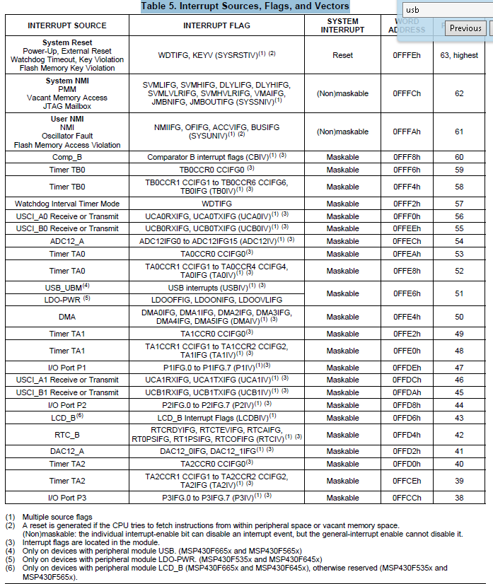
    Whereas Table 5. Interrupt Sources, Flags, and Vectors in the SLAS700C datasheet which covers the MSP430F665x, MSP430F645x, MSP430F565x, MSP430F535x series of devices shows that there is one interrupt vector which is used for either the LDO or USB depending upon the type of device (the MSP430F5359 has the LDO and not the USB):

    By counting the same interrupt vector twice for USB and LDO in the ProxyVectorTable has caused the other entries to be out of step.

    I have been getting confused by the comments in the ProxyVectorTable and Vector_Table, so will try re-writing the tables from scratch.

  • Hi Chester,

    Many thanks again for your quick reply! We totaly looked over that, thank you! A question about the LCD_B interrupt, this is a reserved space (of four bytes?) on the MSP430F5359 variant. If we just leave the BRA instruction with a empty dummy ISR call that would be fine?

    By rewriting from sractch did you mean that you will do that or that we will do that and we post it here?

    Thank you again for your help!
  • Roy Stegers said:
    . If we just leave the BRA instruction with a empty dummy ISR call that would be fine?

    Yes.

    Roy Stegers said:
    By rewriting from sractch did you mean that you will do that or that we will do that and we post it here?

    I was going to re-write from scratch and then post here - to give you something to cross-check against.

  • Hi Chester,

    If you could write an reference example than that would be great! Thank you for all your help! We are looking forward on the example post!

    Many thanks in advance!
  • Roy Stegers said:
    If you could write an reference example than that would be great!

    I created the following Vector_Table using the content from the CCS 6.0.1 msp430f5359.h include file, and I have checked the comments against the MSP430F5359 data sheet:

    /* The MSPBoot Vector Table for a MSP430F5359 */
    #   ifdef __IAR_SYSTEMS_ICC__
    #       pragma location="BOOT_VECTOR_TABLE"
    __root const uint16_t Vector_Table[] =
    #   elif defined (__TI_COMPILER_VERSION__)
    #       pragma DATA_SECTION(Vector_Table, ".BOOT_VECTOR_TABLE")
    #       pragma RETAIN(Vector_Table)
    const uint16_t Vector_Table[] =
    #   endif
    {
    	APP_PROXY_VECTOR(0),  /* 0xFFC6 USCI B2 Receive/Transmit */
    	APP_PROXY_VECTOR(1),  /* 0xFFC8 USCI A2 Receive/Transmit */
    	APP_PROXY_VECTOR(2),  /* 0xFFCA Port 4 */
    	APP_PROXY_VECTOR(3),  /* 0xFFCC Port 3 */
    	APP_PROXY_VECTOR(4),  /* 0xFFCE Timer2_A5 CC1-4, TA */
    	APP_PROXY_VECTOR(5),  /* 0xFFD0 Timer2_A5 CC0 */
    	APP_PROXY_VECTOR(6),  /* 0xFFD2 DAC12 */
    	APP_PROXY_VECTOR(7),  /* 0xFFD4 RTC */
    	UNUSED,               /* 0xFFD6 reserved */
    	APP_PROXY_VECTOR(8),  /* 0xFFD8 Port 2 */
    	APP_PROXY_VECTOR(9),  /* 0xFFDA USCI B1 Receive/Transmit */
    	APP_PROXY_VECTOR(10), /* 0xFFDC USCI A1 Receive/Transmit */
    	APP_PROXY_VECTOR(11), /* 0xFFDE Port 1 */
    	APP_PROXY_VECTOR(12), /* 0xFFE0 Timer1_A3 CC1-2, TA1 */
    	APP_PROXY_VECTOR(13), /* 0xFFE2 Timer1_A3 CC0 */
    	APP_PROXY_VECTOR(14), /* 0xFFE4 DMA */
    	APP_PROXY_VECTOR(15), /* 0xFFE6 LDO Power Management event */
    	APP_PROXY_VECTOR(16), /* 0xFFE8 Timer0_A5 CC1-4, TA */
    	APP_PROXY_VECTOR(17), /* 0xFFEA Timer0_A5 CC0 */
    	APP_PROXY_VECTOR(18), /* 0xFFEC ADC */
    	APP_PROXY_VECTOR(19), /* 0xFFEE USCI B0 Receive/Transmit */
    	APP_PROXY_VECTOR(20), /* 0xFFF0 USCI A0 Receive/Transmit */
    	APP_PROXY_VECTOR(21), /* 0xFFF2 Watchdog Timer */
    	APP_PROXY_VECTOR(22), /* 0xFFF4 Timer0_B7 CC1-6, TB */
    	APP_PROXY_VECTOR(23), /* 0xFFF6 Timer0_B7 CC0 */
    	APP_PROXY_VECTOR(24), /* 0xFFF8 Comparator B */
    	APP_PROXY_VECTOR(25), /* 0xFFFA User Non-maskable */
    	APP_PROXY_VECTOR(26)  /* 0xFFFC System Non-maskable */
    };
    

    The ProxyVectorTable with your used interrupt vectors is:

    /*! This is a "proxy" interrupt table which is used by the bootloader to jump to
        each interrupt routine.
        It always resides in the same location.
        It uses inline assembler to be able to encode BRA instructions to 20-bit addresses,
        so the interrupt function may be placed in lower or upper memory.
        Note that the number and location of each vector should match the declaration
        in Boot's Vector_Table
        Unimplemented vectors are removed (and unused vectors can be removed too)
        to save flash space
        The following table matches the vectors for MSP430F5359
    */
    __asm (" .sect .APP_PROXY_VECTORS");
    __asm (" .retain .APP_PROXY_VECTORS");
    __asm (" .global ProxyVectorTable");
    __asm ("ProxyVectorTable:");
    __asm (" BRA #USCI_B2_ISR;");      /* APP_PROXY_VECTOR(0)  USCI B2 Receive/Transmit */
    __asm (" BRA #Dummy_Isr;");        /* APP_PROXY_VECTOR(1)  USCI A2 Receive/Transmit */
    __asm (" BRA #Dummy_Isr;");    	   /* APP_PROXY_VECTOR(2)  Port 4 */
    __asm (" BRA #Dummy_Isr;");        /* APP_PROXY_VECTOR(3)  Port 3 */
    __asm (" BRA #Dummy_Isr;");        /* APP_PROXY_VECTOR(4)  Timer2_A5 CC1-4, TA */
    __asm (" BRA #Dummy_Isr;");        /* APP_PROXY_VECTOR(5)  Timer2_A5 CC0 */
    __asm (" BRA #Dummy_Isr;");        /* APP_PROXY_VECTOR(6)  DAC12 */
    __asm (" BRA #Dummy_Isr;");    	   /* APP_PROXY_VECTOR(7)  RTC */
    __asm (" BRA #Dummy_Isr;");    	   /* APP_PROXY_VECTOR(8)  Port 2 */
    __asm (" BRA #USCI_B1_ISR;");	   /* APP_PROXY_VECTOR(9)  USCI B1 Receive/Transmit */
    __asm (" BRA #Dummy_Isr;");    	   /* APP_PROXY_VECTOR(10) USCI A1 Receive/Transmit */
    __asm (" BRA #Dummy_Isr;");    	   /* APP_PROXY_VECTOR(11) Port 1 */
    __asm (" BRA #TIMER_INTERRUPT;");  /* APP_PROXY_VECTOR(12) Timer1_A3 CC1-2, TA1 */
    __asm (" BRA #TIMER_INTERRUPT;");  /* APP_PROXY_VECTOR(13) Timer1_A3 CC0 */
    __asm (" BRA #Dummy_Isr;");    	   /* APP_PROXY_VECTOR(14) DMA */
    __asm (" BRA #Dummy_Isr;");    	   /* APP_PROXY_VECTOR(15) LDO Power Management event */
    __asm (" BRA #Timer_A0;");         /* APP_PROXY_VECTOR(16) Timer0_A5 CC1-4, TA */
    __asm (" BRA #Timer_A0;");         /* APP_PROXY_VECTOR(17) Timer0_A5 CC0 */
    __asm (" BRA #Dummy_Isr;");    	   /* APP_PROXY_VECTOR(18) ADC */
    __asm (" BRA #USCI_B0_ISR;");      /* APP_PROXY_VECTOR(19) USCI B0 Receive/Transmit */
    __asm (" BRA #Dummy_Isr;");    	   /* APP_PROXY_VECTOR(20) USCI A0 Receive/Transmit */
    __asm (" BRA #Dummy_Isr;");    	   /* APP_PROXY_VECTOR(21) Watchdog Timer */
    __asm (" BRA #Dummy_Isr;");    	   /* APP_PROXY_VECTOR(22) Timer0_B7 CC1-6, TB */
    __asm (" BRA #Dummy_Isr;");    	   /* APP_PROXY_VECTOR(23) Timer0_B7 CC0 */
    __asm (" BRA #Dummy_Isr;");    	   /* APP_PROXY_VECTOR(24) Comparator B */
    __asm (" BRA #Dummy_Isr;");    	   /* APP_PROXY_VECTOR(25) User Non-maskable */
    __asm (" BRA #Dummy_Isr;");    	   /* APP_PROXY_VECTOR(26) System Non-maskable */
    

    The boot vector table MEMORY in the linker command file is set to the following to match the Vector_Table:

        // Boot vector Table from __Boot_VectorTable- __Boot_Reset
        INT_VECTOR_TABLE        : origin = 0xFFC6, length = 0x38
    

    The length of the APP_PROXY_VECTORS memory in the linker command file needs to be 0x6c (27 entries of 4 bytes) to match the ProxyVectorTable.

    I have checked this several times, but don't have an actual MSP430F5359 to test with. As I suggested previously, setting a breakpoint on the Dummy_Isr in the application and checking that the breakpoint isn't hit is a way of validating the interrupt vector setup isn't offset.

  • Hi Chester,

    Just want to let you know that last week we didn't had the chance to try the new proxy table, we have some high priorty customer issues that we are working on. We hope to have a change this week, and we keep you posted!

    Many thanks for your help!
  • Hi Chester,

    Yesterday we had finally time to adjust the proxy table and the bootlaoder it seems to work with a small application! Now we are trying to get it to work with or target application, when we load in our application and the bootloader then everything workes fine!

    We only have a problem when we load in the actual application annd want to swap it with a new apllication. Then the copy from the download area to the application area seems to go fine ( checksums are calculated and are correct) but when right after that we want to jump to the application and then the program hangs.

    Does the application needs to initialize the DCO and timers? Or must the bootloader do this? We think that the DCO faultflags are not cleared.

    This is strange because when we only load in the bootloader and write in the download the space the new firmware (the application space is empty) then the copying from the download space to the application space goes fine and it jumps to the application after writing.

    Do you have any idea what the problem might be?

    Thank you for all your help so far!
  • Hi Chester,

    After some thinnking we where wondering if it could be that when replacing the old application code with the new application code that the BRA instructions in the proxy vector table could me miss alligned?

    Both the old and the new application have the exact same linker file, infact the are both the same for one minor diffrence. The new code plays a buzzer sound to let us know that the now code is succesfully loaded. The rest of the code is exactly the same.

    Could this be the reason why the new application is not started after the old one is replaced? Before writing we also check if the erasing of the application space is done and after writing we check the checksum, both checks are fine. Our could it be the intialisation of the DCO and timers?

    Hope you might find the time to answer our questons, many thanks in advance!
  • Roy Stegers said:
    After some thinnking we where wondering if it could be that when replacing the old application code with the new application code that the BRA instructions in the proxy vector table could me miss alligned?

    Looking at the MSPBoot documentation the Proxy Table is part of the App Area, so would expect the Proxy Table to be updated with the application code and thus remain consistent.

    Roy Stegers said:
    Our could it be the intialisation of the DCO and timers?

    It is difficult to give advice without more details. Do both the MSPBoot/AppMgr and Application attempt to initialize the DCO and timers?

    Are you able to post a complete example project which demonstrates the problem?

    [The target examples in MSPBoot are for FR5739 and G2x55x devices]

  • Hi Chester,

    Once again thank you for your reply!
    Is it possible to send you our project directly via mail? If so then could you message me te e-mail address where we can send it to? Else we could make a general example and post it here, please let us know what you preffer.

    About the intialisation, we are trying both, we are not sure wat is the best (initialisation of DCO and timers in bootloader or in the application). We think in the bootloader is better(?) because that part is always started first. Also after erasing and wring the new application is it better to jump to the actual application or to use BOR to restart(causing the reenter te bootloader and possibly initialise the whole MCU again).

    Thank you so far!
  • Roy Stegers said:
    If so then could you message me te e-mail address where we can send it to?

    I have sent a private message with my email address.
    Roy Stegers said:
    About the intialisation, we are trying both, we are not sure wat is the best (initialisation of DCO and timers in bootloader or in the application). We think in the bootloader is better(?) because that part is always started first.
    If the DCO is initialized in the application, then the settings could be changed in an application update, where if done only in the bootloader the DCO settings can't be changed with a new application.

    For the timers, does the bootloader enable interrupts? Enabling interrupts in the bootloader, before the application is called, might cause issues.

    Roy Stegers said:
    Also after erasing and wring the new application is it better to jump to the actual application or to use BOR to restart(causing the reenter te bootloader and possibly initialise the whole MCU again).

    I think using the BOR would be better, since it reset the device to a known state. The MSPBoot documentation suggests that a BOR is issued in response to the bootloader receiving a "Jump To Application" message.

    [When looking at the MSPBoot examples I was getting confused since there is the similarly named TI_MSPBoot_AppMgr_JumpToApp which is a function which generates a software BOR and the macro TI_MSPBoot_APPMGR_JUMPTOAPP which jumps to the application reset vector]

    One other thought - after the application fails to start, can you attach the debugger to the running device, as described in http://processors.wiki.ti.com/index.php/MSP430_-_Connecting_to_a_running_target  , to see what is the state of the device?

  • Hi Chester,

    Thank you for your reply!

    We have made a small test example, the only real diffrence is that is that the actual project is greater in size. The core steps are the same. We have mailed it you directly.
  • Hi Chester,

    Did you receive our e-mail (we where just wondering)? Else we will send it again ;).
  • Roy Stegers said:
    Did you receive our e-mail (we where just wondering)?

    Yes, I received your email with the code. I looked at the source code, but haven't yet identified what causes the new application to fail to restart after the reboot.

    When the new application fails to start, can you attach the CCS debugger to try and find the state of the failed program and/or single step from a device reset to find at what point the failure occurs?

    I haven't got the same MSP430F5359 device to try your example program unmodified, but will try running on a different device to see if can repeat the failure so can investigate.

  • Hi Chester,

    Thank you for your reply, today and probaly tommorow we have some high priority customer issues to solve. We hope to continue our work on the bootloader at the end of tommorow.

    We will attach the debugger when the application failes to start.

    We have a debug related question:

    When the bootloader is loaded and there is an application in the app space. Can we step trough the actual application code(since the bootloader project is loaded with CSS with debug view and not the application project). When we jump to the application form the bootloader the debugger does not step with it (which is because the bootloader project is loaded via CSS debugger?).

    Is there a way to debug the application when using a main memory bootloader?

    Once again many thanks for your help!
  • Roy Stegers said:
    Is there a way to debug the application when using a main memory bootloader?

    After the bootloader project debug has started, try Run -> Load -> Add Symbols and load the symbols from the application .out file. The debugger should then know about the symbols from the application project, as well as the symbols from the bootloader project.

  • Hi Chester,

    Just want to let you know that everything works the way we wanted regarding the bootloader. We want to thank you once more for all your help.

    Many thanks!

**Attention** This is a public forum