This thread has been locked.

If you have a related question, please click the "Ask a related question" button in the top right corner. The newly created question will be automatically linked to this question.

Webench offers differnt solutions compared with my October 2013 designs

Other Parts Discussed in Thread: TPS54622

Hi,

I revise my board layout that contains 4 TPS54622. Playing around with some parameter, I recognized that the same parameter as I used in October will now offer different solutions.

The Ccomp2 is new, and L1 and Cout have higher values. What is the reason for this?
 Is it recommended to regenerate all designs?

Bahne

  • I have some additional Information to my post of yesterday:

    Both designs have the same WEBENCH input parameter. The first one is from today and second from October (working fine)

    5810.webench_design_523997_25_892095342.pdf

    8623.webench_design_1V-4A5.pdf

  • Hello Bahne,

    Thanks for this query. Someone from our team will respond very soon.

    Thanks.

  • Bahne,

    I am unaware of any changes to the inductor selection. We update our passive component database often and it may be possible this resulted in picking a different inductor based on the knob settings in the optimizer for the new design.

    However, upon looking at the history, the output capacitor and compensation network have incurred some changes. For example, in October '13, we used only Rcomp, Ccomp but now we also use Ccomp2 in addition. This was based on feedback from the users where the phase margin was not sufficient in some cases.

    It would be good to create designs again if you can for future use. I apologize for the inconvenience caused and we will notify you of any changes to device(s) in the future.

    Please do let me know if you have any further questions or need any assistance.

    Regards,

    Amod Vaze

  • Hi Amod,
     
    Thank you for your information. My problem is, that I am not an expert in converter design and so I trusted the
    WEBENCH output. My board with 4 TI converter is running fine, but I want to increase the current for one
    converter.
    It is a bad feeling when the WEBENCH now offers different results. But I hope you can help me.
    In the attached screenshot, you can see my existing design on top and my desired design below.

    1.       is it possible to take two times the 22µF capacitor for Cin?

    2.       is it really necessary to have two times 220µF for Cout?

    3.       what is the risk, when I use the old compensation circuit without Ccomp2?

    4.       do you recommend to run the new WEBENCH for the other 3 converter?

     
    Thank you
     
    Bahne
     
    Von: Amod Vaze [mailto:bounce-1137857@mail.e2e.ti.com]
    Gesendet: Mittwoch, 25. Juni 2014 21:59
    An: analog_elab@mail.e2e.ti.com
    Betreff: RE: [Webench Tools Forum] Webench offers differnt solutions compared with my October 2013 designs
     

    Bahne,

    I am unaware of any changes to the inductor selection. We update our passive component database often and it may be possible this resulted in picking a different inductor based on the knob settings in the optimizer for the new design.

    However, upon looking at the history, the output capacitor and compensation network have incurred some changes. For example, in October '13, we used only Rcomp, Ccomp but now we also use Ccomp2 in addition. This was based on feedback from the users where the phase margin was not sufficient in some cases.

    It would be good to create designs again if you can for future use. I apologize for the inconvenience caused and we will notify you of any changes to device(s) in the future.

    Please do let me know if you have any further questions or need any assistance.

    Regards,

    Amod Vaze

  • Hi Bahne,

    I did not get the screenshots in your reply. Could you please send it out as an attachment? I can take a look and answer your questions.

    When it comes to number 3. Ccomp2 was used mainly to add a higher frequency pole to get rid of any noise. This is not always required especially if you have a good gain margin with a nice layout. However, adding Ccomp2 can add a margin of safety.

    Regards,

    Amod Vaze

  • Hi Amod,
     
    my mail of Do 26.06.2014 12:28 had the "Regler25.gif". I have attached it again and I copy it into the message body:
     
     
    With best regards
     
    Bahne
     
    Von: Amod Vaze [mailto:bounce-1137857@mail.e2e.ti.com]
    Gesendet: Donnerstag, 26. Juni 2014 20:54
    An: analog_elab@mail.e2e.ti.com
    Betreff: RE: [Webench Tools Forum] Webench offers differnt solutions compared with my October 2013 designs
     

    Hi Bahne,

    I did not get the screenshots in your reply. Could you please send it out as an attachment? I can take a look and answer your questions.

    When it comes to number 3. Ccomp2 was used mainly to add a higher frequency pole to get rid of any noise. This is not always required especially if you have a good gain margin with a nice layout. However, adding Ccomp2 can add a margin of safety.

    Regards,

    Amod Vaze

  •  

    Hi Bahne,

    I still did not get the image. I just see this message: '<!--[if !mso]><![endif]--><!--[if gte mso 9]>< ![endif]--><!--[if gte mso 9]>< ![endif]-->'  instead of your attached gif.

    Could you repeat the procedure when you attached the pdf documents before? I am also attaching a snapshot to help attach the file using  the 'Insert file'  icon above. You can also zip the gif file before sending it. Give this a try - hopefully, it works.

    Regards,

    Amod Vaze


  • Hi Amod,

    I think it will only work online.

    Bahne

  • Hi Bahne,

    This time the schematics came through.

    1. Yes, you can change the input capacitor Cin by using the 'BOM' tab and 'Select Alternate Part'. You could pick the GRM32ER61E226KE15L which is a 22uF capacitor.

    2. The Cout value depends on your requirement. If you would like to go lower, it would be good to make sure the output ripple and load transient specifications are still met. Do you have any stringent requirements? I could go lower to say 200uF/7mohm capacitor like a EEF-UE0J221LR.

    3. Depending on the changes you make to the Cout, the compensation network comprising of Rcomp, Ccomp and Ccomp2 needs to be updated. For a 220uF/7mohm EEF-UE0J221LR capacitor at the output, i would recommend Rcomp - 9.76kohm, Ccomp-33nF, Ccomp2 - 51pF. This should give you a 27kHz crossover frequency and 64 degree phase margin. Also, the gain margin is nicely poised at more than 40dB.

    4. If you have a big design change for your other converters, i would recommend recreating your designs again.

    If you would like, I can share my design with you if you can provide your email address you use to login into WEBENCH.

    Hope this helps.

    Regards,

    Amod

  • Hi Bahne,

    I am attaching the design report your reference.

    Regards,

    Amod

    2133.TPS54622_updated_design.pdf

  • Hi Amod,
     
    Thank you very much for your help.
    As Cout I can use the AMK325ABJ227MM-T (Taiyo Yuden 4V X5R 220µF ). I think it has less than 7m ESR but I do not know.
    As the inductor, I need to use the Coilcraft SER2009-202MLB because all other converter also have it.
    It has 2.µH and 630.0 µΩ.
    Can I just change this components and leave all other?
     
    With best regards
     
    Bahne
     
    Von: Amod Vaze [mailto:bounce-1137857@mail.e2e.ti.com]
    Gesendet: Freitag, 27. Juni 2014 21:15
    An: analog_elab@mail.e2e.ti.com
    Betreff: RE: [Webench Tools Forum] Webench offers differnt solutions compared with my October 2013 designs
     

    Hi Bahne,

    I am attaching the design report your reference.

    Regards,

    Amod

    2133.TPS54622_updated_design.pdf

  • Hi Bahne,

    That is a ceramic capacitor and will derate in its value over the applied voltage of 2.5V. I could not find the exact derating but if we assume a linear derating, the output will only see about 132uF of capacitor value. I recompensated for the new capacitor and would recommend a lower Rcomp - 6.49kohm, Ccomp-22nF and Ccomp2-33pF. You should see about the same frequency loop response behavior as before with this new compensation. The inductor should be fine.

    Please let me know if you have any further questions.

    Best Regards,

    Amod

  • Hi Amod,

    I am still not happy with the Webench result for my converter. If you compare the columns in the attached table, you see that in cannot be serious results. The column F shows the Cout value when you run the Webench with exactly the same input parameter as I used in 2013.

    Additionally I did a mistake and used only one 22µF capacitor for the 1V and 1,5V regulator, but they are working fine. Especially for 1V converter, we did extended measurings and found that the ripple is inside the tolerance range, even there was a Cout with half of the calculated capacity.

    So the current Webench result say that I should use 20 times the capacity. I cannot trust this.

    Perhaps the special thing for me is, that we have power planes that have 50µ distance to the ground plane. This will add a parallel capacitor with almost no ESR.

    What can I do now?

    For the thre converter (1V, 1,5V and 3,3V) I can use the results from last year, but for the 2,5V I need to increase the curren to 4,75A.

    With best regards

    Bahne

  • Hi Bahne,

    I am looking into the capacitor selection. We could do with a lower value than the 220uF. We can reduce the value in your case with the 2.5 Volts at the output specifically. I tried recreating your design by inputting the 2.5Vo at 4.75A case. However, I was not able to get the inductor and capacitor matching exactly. Can you also mention your switching frequency? Once you provide that, we can change the output capacitor to meet your needs and then recompensate the design.

    Best Regards,
    Amod Vaze

  • Hi Amod,

    Thank you very much for your fast response. We han an external clock with 550 kHz. The Inductor should be:

    Coilcraft SER2009-202MLB  L= 2.0µH  DCR= 630µOhm.

    Can I provide anything?

    Thank you

    Bahne

  • Hi Bahne,

    I took into account the 550kHz frequency and using eq (22) on page 21 of datasheet, with 50% Ioutmax and 5% Vout transient voltage change, you get about 69uF of output capacitance requirement. You could change the numbers as per your requirement.

    I have attached the design report for 66uF/3mohm capacitor which is custom. You could use similar capacitance on your board. After inserting that capacitor and the inductor you mentioned as custom components, recompensation (Hit 'Re-Comp' button on top and specify your target crossover and phase margin. I used 30kHz and 60deg Phase Margin following which I saved the design.) yields a new compensation network.

    Please check this design and let me know if you have any more concerns.

    Regards,

    Amod Vaze

    7827.TPS54622 2p5 Vo design.pdf


  • Hi Amod,
     
    Thank you very much for your information and for the complete design.
    It will need a while until we will have the revised schematic.
    I will inform you, once I have the Layout revision complete.
     
    Generally, do you have more information, why the Webench now offers such
    different results. There must have been changes in the simulation models
    and parameters.
    How can one trust the results when they will change more than 10 times in their valus.
    I am very much interested in this, but it is actually not necessary for my work.
     
    With best regards
     
    Bahne
     
     
    Von: Amod Vaze [mailto:bounce-1137857@mail.e2e.ti.com]
    Gesendet: Montag, 28. Juli 2014 20:07
    An: analog_elab@mail.e2e.ti.com
    Betreff: RE: [Webench Tools Forum] Webench offers differnt solutions compared with my October 2013 designs
     

    Hi Bahne,

    I took into account the 500kHz frequency and using eq (22) with 50% Ioutmax and 5% Vout transient voltage change, you get about 69uF of output capacitance requirement. You could change the numbers as per your requirement.

    I have attached the design report for 66uF/3mohm capacitor which is custom. You could use similar capacitance on your board. After inserting that capacitor and the inductor you mentioned as custom components, recompensation (Hit 'Re-Comp' button on top and specify your target crossover and phase margin. I used 30kHz and 60deg Phase Margin following which I saved the design.) yields a new compensation network.

    Please check this design and let me know if you have any more concerns.

    Regards,

    Amod Vaze

    7827.TPS54622 2p5 Vo design.pdf


  • Hi Bahne,

    Yes, please do let me know if you need any more assistance with this design. I believe the transient requirement on the new WEBENCH designs was more stringent. About 2.5% Vout change for ful load change causing the cap to be larger. This was necessary especially for low output voltages as we were seeing shutdown cases where the load transient was causing the voltage to go down below the power good requirement.


    Regards,

    Amod Vaze

  • Hi Amod,

    I try to use your information to get my designs, but I need some more information:

    1. When I try to open one of my existing designs, I always get the design at its inital status and all my changes are lost. I found a button "Save Name and Notes" but no button to save the design.

    2. I use "Create a Custom Part" GRM32ER60J107ME20L, 100µF 6.3V as Cout. Here I do not know how to calculate the value for "IRMS".

    3. The value for ESR depens on frequency - at which frequency have I to take the ESR value?

    With best regards

    Bahne

  • Hi Bahne,

    1. The saved designs are under My designs/projects on the upper left corner once inside the tool. Those designs are in same state as you last left them unless you modify the switching frequency or soft-start time in this case (TPS54622). If you are not changing any conditions, then we might have to dig deeper to find the cause of the discrepancy.

    2. When it comes to the IRMS and ESR values for your GRM32ER60J107ME20L. Since it is a ceramic, you could use a nominal ESR of 0.003 and a non-zero IRMS, like say 3A. This ESR should not change the way the tool predicts the behavior much as a ceramic cap's power dissipation is typically low.

    What you might want to be careful about is the capacitance value itself. Please refer to page 14 of the attached datasheet and depending on your output voltage, you might want to lower the 100uF to the correct value. For example, with the GRM32ER60J107ME20L, let us say with 3.3Vout, the value of the caapcitor will drop down by ~50% ( 50uF).

    Please let me know if you any more assistance.

    Best Regards,

    Amod Vaze

    6320.GRM32ER60J107ME20-01.pdf

  • Hi Amod,
     
    I am in hurry now and I accidentally clicked "Stop receiving emails" – how can I activate receiving e-mails again?
     
    Tahnk you
    Bahne
     
    Von: Amod Vaze [mailto:bounce-1137857@mail.e2e.ti.com]
    Gesendet: Mittwoch, 13. August 2014 20:10
    An: analog_elab@mail.e2e.ti.com
    Betreff: RE: [Webench Tools Forum] Webench offers differnt solutions compared with my October 2013 designs
     

    Hi Bahne,

    1. The saved designs are under My designs/projects on the upper left corner once inside the tool. Those designs are in same state as you last left them unless you modify the switching frequency or soft-start time in this case (TPS54622). If you are not changin any conditions, then we might have to dig deeper to find the cause.

    2. When it comes to the IRMS and ESR values for your GRM32ER60J107ME20L. Since it is a ceramic, you could use a nominal ESR of 0.003 and a non-zero IRMS, like say 3A. This ESR should not change the way the tool predicts the behavior much as a ceramic cap's power dissipation is typically low.

    What you might want to be careful about is the capacitance value itself. Please refer to page 14 of the attached datasheet and depending on your output voltage, you might want to lower the 100uF to the correct value. For example, with the GRM32ER60J107ME20L, let us say with 3.3Vout, the value of the caapcitor will drop down by ~50% ( 50uF).

    Please let me know if you any more assistance.

    Best Regards,

    Amod Vaze

  • Hi Bahne,

    You can unmute the thread again by signing into the forum.

    Once you get to this post in the forum, check the 'Options' on the left side where you can see 'Unmute Thread'. Click on that and you should be good to go.

    Regards,

    Amod Vaze

  • Hi Amod,

    I think the behavior of the Webench program depends on the health of the Adobe Flash Player.
    I did changes on Cin, Cout and L and sometimes all Parameter from one part are set to default.

    I still do not know how to save a design that I like.

    Thank you for your helpful information regarding IRMS and ESR.

    I do not worry on the Cout capacitance because there is a factor 20 between my running design and the Webench recommendation (before August 6).

    So  as long as the capacitance has no influence on the compensation circuit, I am fine.

    In other words, do you recommend to change the Cout capacitance in the Webenchto get correct values for the compensation circuit?

    I will attach the report from the design I want to use. Do you think that design is ok?


    Thank you

    Bahne

      0285.webench_Mi_03_BINGO.pdf

  • Hi Bahne,

    Output Capacitance is important for the compensation design. The 100uFX2 cap in the pdf has a DC Voltage rating of 4V. Assuming linear derating, the value of the 100uFX2 will fall down to a total of about 75uF. Using that, the pdf design is not going to be stable enough (~19 deg phase margin). WIth the derating accounted for, you can use Rcomp=3.83kohm, Ccomp =47nF, and Ccomp2= 39pF. That should give you around 30kHz crossover with 62 deg phase margin which is good. So, you can continue with the same Cout now but use the new compensation.

    Regards,

    Amod

  • Hi Amod,

    Thank you very much for your Info and it is great that you have calculated the compensation circuit for me.  Now I can relaxed build the 2.5V circuit.

    For the three remaining circuits (1V, 1.5V, 3.3V), it was my plan to leave this circuits as they were calculated with the last year Webench version. But with your information I became uncertain and would not expect that the circuits would run. On the other hand I have 8 boards were they are running fine.

    So I must have something in my environment that helps to compensate errors in the circuit design.

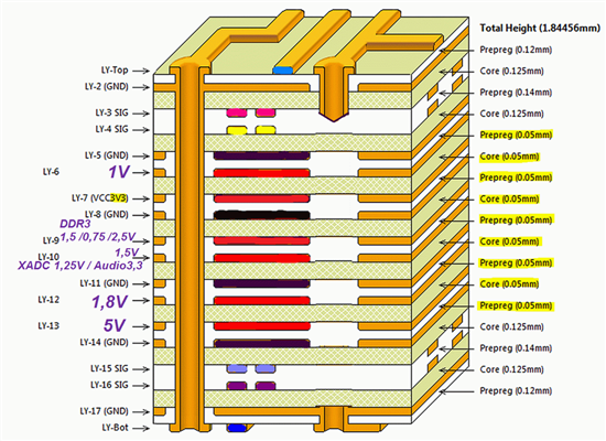
    First I have a Power Distribution System built up with Power Layers that have 50µm distance to the ground plane and so build up a capacitor with super good AC properties. The area of the planes is 180 cm2 ( 0,018 square meter) and offers a capacity of 13nF. I will attach a a sketch from my Layer Stack.

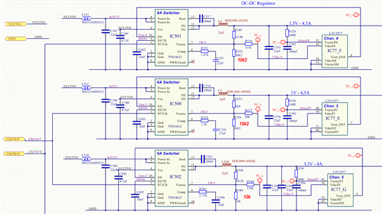
    Second I use a power controller (LTC2977) that has influence on the Vsense Input.

    I will attach the schematic where the 1V Regulator is in the center. The R517 is the resistor, where the Power Controller has access to the Vsense Input. It measures the Output voltage (R530 and C582) and regulates it with its DAC Output (Pin 50).

    I will also attach the Webench printout from June 2013.

    Please note that it has 2 capacitors for Cout and I accidentally have only one in my real design (C356).

    What do you recommend? Shall I just add one 22µF capacitor to have the design according to the June 2013 Webench output?

    Thanks, Bahne


    3465.webench_design_1V-4A5.pdf

  • Hi Amod,

    I just got the permission from Nils Dirks to forward his his measuring results he presented. He compared the ZedBoard with my board and and did special measuring at the 1V supply.

    Please see page 8 - 15.

    Best regards

    Bahne

    0250.PI&SI_2.pdf