This thread has been locked.

If you have a related question, please click the "Ask a related question" button in the top right corner. The newly created question will be automatically linked to this question.

TPS55340 SEPIC simulation in TINA-TI

Other Parts Discussed in Thread: TPS55340EVM-147, TPS55340, TINA-TI

I'd like to simulate TPS55340 SEPIC design in TINA-TI. Just to get started I've used the same schematic as in TPS55340EVM-147 kit. However the simulation doesn't work properly: there is no switching and the output voltage rises to strangely high values.

I've upload the simulation file to dropbox if anyone is willing to take a look.

dl.dropboxusercontent.com/.../tps55340_sepic.tsc

  • Wojciech,

    I believe this has to do with the coupled inductor model being used. I have simulated this EVM previously with the attached .TSC file. Please take a look at it and see if it will meet your needs.

    TPS55340_sepic.TSC

  • Like Britt mentioned, it is important to have a good model of the coupled inductor. The best way to model it is like a transformer. I have updated the attached below with a model I have used in the past. L1 represents the inductance of the transformer. L2 is the leakage inductance and DCR. It is important to include the leakage inductance to match the inductor current waveforms.

    TPS55340_sepic_coupledinductor.TSC

  • Britt,

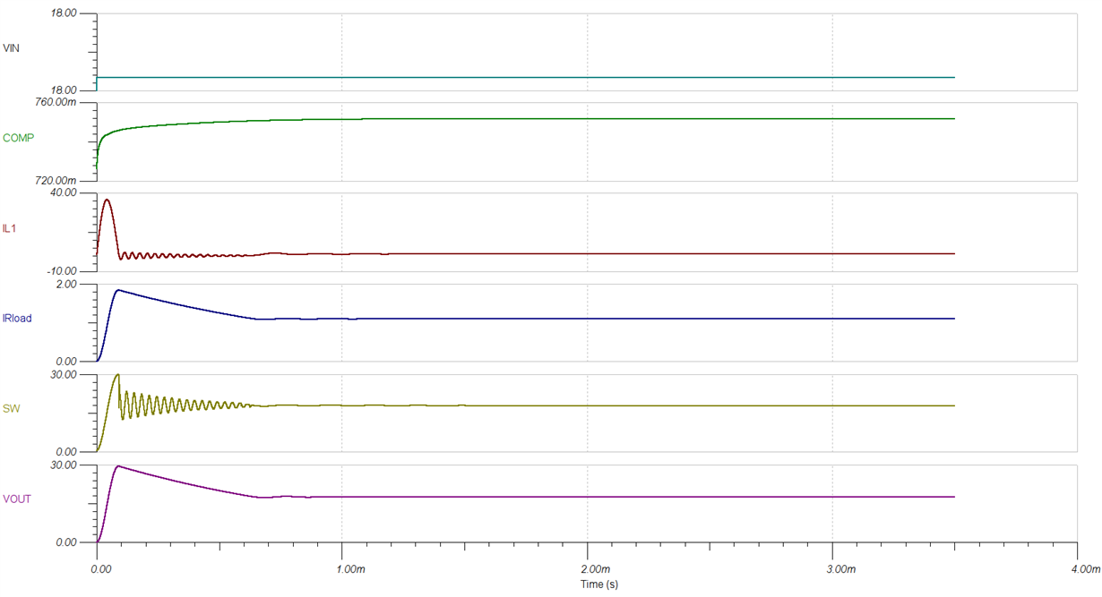
    Thank you for the simulation file.  The simulation runs fine as is. However, when I set the INPUT voltage (Vin=18) above the OUTPUT voltage it doesn't seem to work: there is no switching activity.


    Anthony,

    I've check your file too. It works as is, but when I set the input voltage to 18V the simulation doesn't complete: there is a convergence error.

    BTW, I've the TPS55340EVM-147 and while doing a couple of checks yesterday I've managed to burn the IC somehow. The result of my experiment is that the IC gets hot and draws 2.5A when enabled...

    The input voltage was between 6-18V as per specs. For the test I've used the EVM to power on a device that has a couple of SMPS in it. There is quite a lot input capacitance in the device. Also a cable between the EVM and the device was quite long. Maybe you guys will have an idea what could have gone wrong?

  • Could you describe the step by step process used to power on the EVM and connect the load? I wonder if there was some voltage transients on the input or output causing an over voltage to the power MOSFET.

    I also adjusted the sim below by adding a voltage supply to control the EN pin. This solved the convergence issue. This is just something I knew to try based on past experience.

    TPS55340_sepic_coupledinductor_stepEN.TSC

  • As far as I remember the load was connected. The EN jumper was in the ON position. I've connected a bench power supply to the EVM. The output voltage of the bench power supply was about 12V. I've replaced the IC and so far I haven't experienced a similar problem.


    Thanks for the simulation file. It works fine now.


    I have more questions about using TPS55340 but I'll open a new topic to keep it clear.