This thread has been locked.

If you have a related question, please click the "Ask a related question" button in the top right corner. The newly created question will be automatically linked to this question.

Amplifier Input Current-Noise Density

Other Parts Discussed in Thread: LMV791, TINA-TI, LMH6629

Dear all,

I have one problem for simulating LMV791 to determine the Input Current-Noise Density in PSPICE. Texas Application Report- AN-1516 Pspice Universal Test Circuits (snoa475d.pdf) gives noise testing circuit, and result of output graph. I am able to determine the Input Voltage Noise Density, but I don't know how to determine Input Current-Noise Density as with this given testing circuit and Simulated Current Noise Density curve in PSPICE. 

Thanks in advance,

Phalla

  • Hello, anyone has any idea how to obtain the input current density noise curve of Amplifier in PSPICE, please?

  • Phalla,

    One of our experts here at TI has sent me some information about your question. Hooman Hashemi makes the following observations/recommendations:

    1. Wrong unit: Page 10 noise density plot (labeled as voltage noise) but shows pA/RtHz units!
    2. No datasheet Match: Page 10 LMV791 current noise density plot does not match the flatband noise of ~ 0.01pA/RtHz (no datasheet plot of noise current to compare against).
    3. Page 10 Circuit anomalies: I get unexplained plots when I test the LMV791 (or any device) using the page 10 technique / schematic. I think I observed similar unexplained / complicated results before, and that led me to search for proven techniques that work (some of these are shown in the Analog Wire post below).

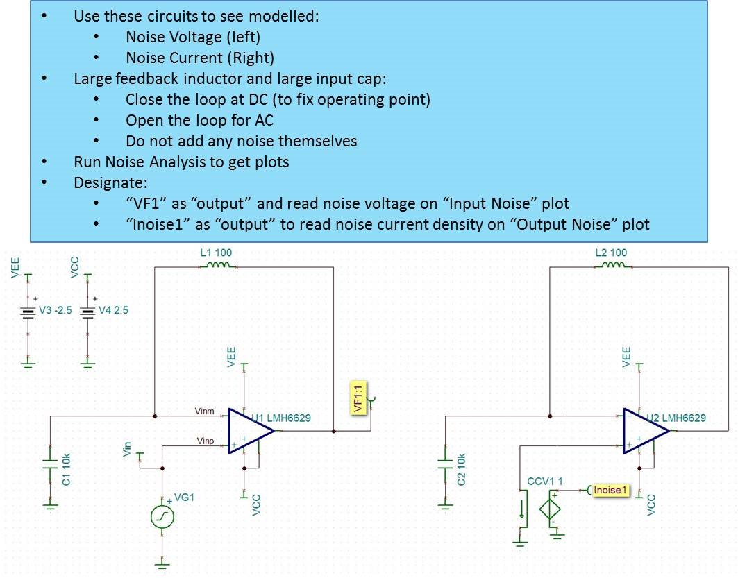
    The TINA file is my attempt at using the technique depicted in the Analog Wire post below related to noise analysis and finding the modeled behavior plot:

    https://e2e.ti.com/blogs_/b/analogwire/archive/2014/04/09/what-you-always-wanted-to-know-about-tina-ti-but-were-afraid-to-ask-part-3

    Specifically, this image / schematic:

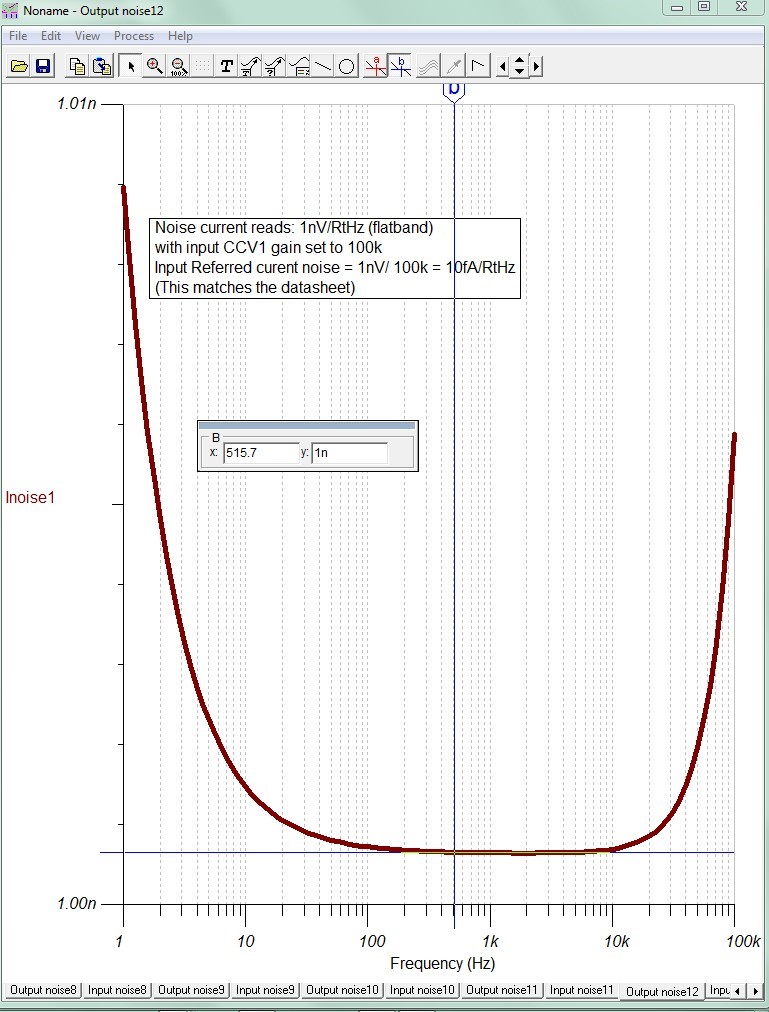
    I can duplicate the noise current density (and noise voltage density as well) of the LMV791 using this technique, as shown here:


    I hope that this information helps.


  • Hello Phala:
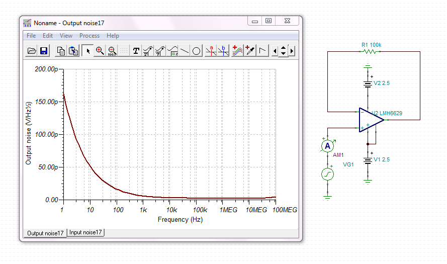
    There's a mistake in the test circuit for current noise. The easiest way is to use the same circuit for voltage noise but insert a 100k resistor with the non inverting terminal.
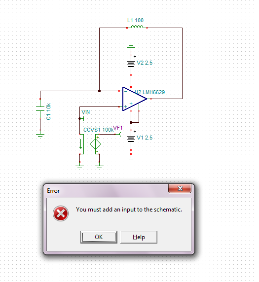
  • Thank Britt for your detail description and your given noise post link. For your given post link, they didn't give a detail description how to test current noise. When I used this test circuit for voltage noise, it work fine as expected but in current noise test circuit, it show error when I am trying to run simulation as alert message box "You must add an input to the schematic". On the other hand, I don't suppose that this test circuit for current noise works with its PSPICE counterpart because the other end of current controlled voltage source is floating (we left no connection to this pin).
  • Thank Soufiane, maybe your recommend current test circuit is as my attach schematic, but I have some questions about this test. There are two output curves, one is output noise and the other one is input noise. They both in unit V/sqr(Hz) not A/sqr(Hz) and which one is the right result for current input noise? If this test circuit is the recommend test circuit for current noise, I don't suppose that I can put current meter the same as TINA-TI in PSPICE counterpart. And do you have any circuit that can be used for testing current noise input in PSPICE.  Thank you.

  • Hi Phala:
    If you want to test current noise, you can simply use the test voltage provided for voltage noise and add large value resistor (100 or 100M) with the non inverting terminal.
    You can also use a current voltage current source as described by my colleague Hooman in his blog.
    e2e.ti.com/.../what-you-always-wanted-to-know-about-tina-ti-but-were-afraid-to-ask-part-3
  • Hello Soufiane, could you please answer my previous questions about the test circuit for voltage noise but insert a 100k resistor with the non inverting terminal? Please, I need the answer.
  • Hello Phalla,

    To see the LMV791 modelled noise current, using the technique in that Analog Wire posting, use this circuit (which is t he same as the one Britt posted earlier, but without the noise voltage portion):

    LMV791 Modeled Noise Current 7_30_16.TSC

    To avoid the error you were getting about specifying one input source, I've added a dummy voltage generator (VG1).

    Regards,

    Hooman

  • Hello Hooman,

    Thank you, your solution saves the day for current noise simulation in Tina-Ti. However, how am I supposed to test current noise of LMV791's PSPICE Model in PSPICE A/D? By using this test circuit in PSPICE, simulation can't accomplish because the other end of CCVS is left open - floating node. May you propose me a current noise test circuit in PSPICE? Thanks,

    Best Regards,

    Phalla

  • Hi Phalla,

    I don't think there are any issues with using that TINA-TI circuit within PSPICE A/D. The floating end of the Current Controlled Voltage source (CCV1) can be tied to a dummy resistor (of any value, as CCV1 can pump infinite current). Use 1k to ground, for example.

    Please try it and let me know if you have any issues.

    Regards,

    Hooman

  • Hello Hooman,

    Thank for your recommendation. Well, there is an issue with using that TINA-TI circuit within PSPICE A/D. Please check my attach files out. I have built the test circuit the same as Tina-Ti and as your recommendation, but one issue is happening during simulation. It said that "ERROR -- Invalid value" above Noise Analysis command. I used LMH6629 for this test. Thank you.

    LMH6629.zip

  • Hi Phalla,

    I'm not an expert on PSPICE A/D.

    Looking at your noise analysis directive:

    .NOISE V(10) VG1 2

    This does not look like any .noise statements I have seen.

    Below I've shown what I was able to find on the web for the syntax required:

    "Syntax: .noise V(<out>[,<ref>]) <src> <oct, dec, lin> <Nsteps> <StartFreq> <EndFreq>

    V(<out>[,<ref>]) is the node at which the total output noise is calculated. It can be expressed as V(n1, n2) to represent the voltage between two nodes. <src> is the name of an independent source to which input noise is referred. <src> is the noiseless input signal. The parameters <oct, dec, lin>, <Nsteps>, <StartFreq>, and <EndFreq> define the frequency range of interest and resolution in the manner used in the .ac directive."

    For example, I don't even see your frequency start and stop specified!

    Please double check to make sure that there is no directive syntax error to begin with.

    Regards,

    Hooman

  • Hello Hooman,

    The syntax that you showed is not the PSPICE's syntax, it's HSPICE syntax. In Noise Analyse, PSPICE requires two commands - one is .AC command and the other one is .Noise command. The parameters <oct, dec, lin> <Nsteps>, <StartFreq>, and <EndFreq> are included in .AC command, so we don't need to include again in .noise as in HSPICE.

    Here is the syntax form of noise analyse in PSPICE:

     .NOISE V(<node> [,<node>]) <name> [interval value]

    Example:  

    .NOISE V(5) VIN

    .NOISE V(101) VSRC 20

    Best Regards,

    Phalla

  • Hello Hooman,

    Do you have a pratical circuit to test the operational amplifier's current noise in Lab or workbench? - I hope there is because most data sheets show current noise data or curve, so there is a practical test probably. Maybe pratical circuit can help me find other solution to simulation current noise in PSPICE. Thanks,

    Best Regards,

    Phalla
  • Hi Phalla,

    Most literature points to using a capacitor in the path of the input bias current (either inverting input or non-inverting input) for measuring CMOS type (femto ampere range) input bias current. The rate of change of output voltage then determines the capacitor / input bias current. You'd also need a switch to discharge the capacitor voltage to begin a new measurement:

    Regards,

    Hooman

  • Hi Phalla,

    I just realized that I answered how to measure CMOS (LMV791) input bias current in the lab, and not how to verify the input noise current! Sorry about my mistake as I was distracted.

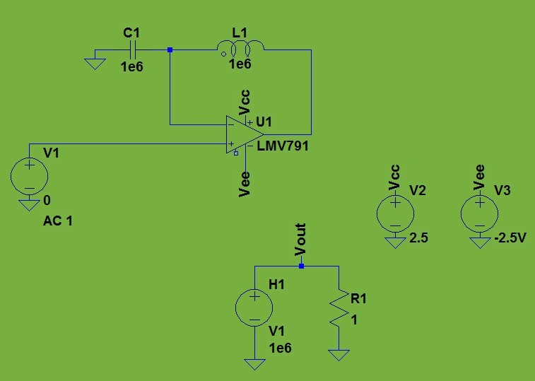
    Going back to your issue with using PSPICE A/D to verify the LMV791 noise curent modeled, I've attached a netlist below which is running on my desktop correctly to show the LMV791 noise current:

    V1 N003 0 0 AC 1 ; voltage source connected to non-inverting input
    V2 Vcc 0 2.5 ; + supply voltage
    XU1 N003 N001 Vcc Vee N002 NC_01 LMV791 ; connections of the LMV791 macromodel
    V3 Vee 0 -2.5V ; - supply voltage
    L1 N002 N001 1e6 ; Large inductor from output to inverting input
    C1 N001 0 1e6 ; Large capacitor from inverting input to ground
    H1 Vout 0 V1 1e6 ; Current dependant Voltage source (transimpedance gain = 1e6 V/Amp) with control current set to input source voltage V1 (tied to non-*inverting input voltage) current. I'll use this large multiplier (1Mohm) to enlarge the small noise current flow in the source (non-inverting input)
    R1 Vout 0 1 ; Dummy resistor where source H1 develops its voltage across (so H1 is not left floating)
    .noise V(Vout) V1 dec 10 1 100k ; Simulating noise from 1Hz to 100kHz with input source V1, and output noise at node Vout (output of H1 dependant source)
    ;op ; Calculate operating point
    ;ac oct 10 1 100Meg
    .lib NSC.lib ; Location of where the LMV791 (XU1) model resides on my PC
    .backanno
    .end

    Here is the schematic:


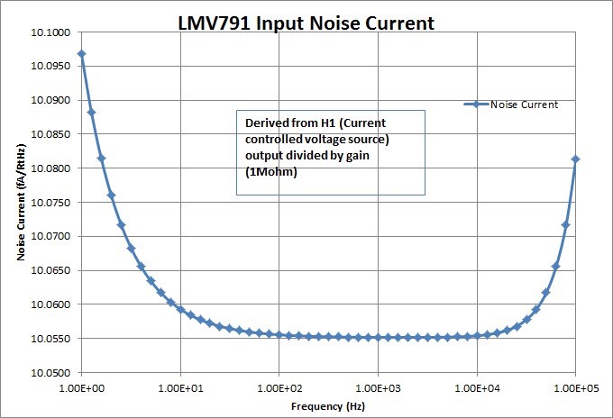
    Here is the resulting noise current waveform (when I divide the output by the H1 gain) showing 10fA/RtHz for the entire range of frequencies:

    Here is the Excel data if you need it:

    LMV791 Noise Current Modeled E2E Hooman 8_9_16.xlsx

    Hope this resolves your issue with PSPICE A/D and you can directly use the Spice netlist above.


    Regards,

    Hooman


  • Hi Phalla,

    I think I see the problem with your original PSPICE A/D file (zip file within your Aug. 1, 2016 post) that is giving you error message!

    You specify the noise input source as VG1 in your netlist .noise statement instead of using the correct one connected to the non-inverting input (node 4) being VSENSE. Here is your netlist:

    VG1 11 0 DC 0 AC 1 ; this source is not connected to the LMV791 setup in any way!
    RG1 11 0 1k

    * AC sweep from 1 Hz to 100 MHz with a decade increment and 1 point per decade
    .AC DEC 100 1 100M

    * Noise analysis
    .NOISE V(10) VG1 2 ; You've specified the input noise source as VG1 which does not have any relationship with the circuit at hand (LMV791)!

    I think if you change your .NOISE statement to call out VSENSE as your input noise voltage source, your error should go away. Below is from your netlist where you define the control current as VSENSE tied to node 4 (non-inverting input of LMV791). VG1 is superfluous and can be entirely deleted (along with RG1).

    VSENSE 4 0 DC 0
    HSENSE 10 0 VSENSE 1

    Please let me know.

    Regards,

    Hooman

  • Hello Hooman,

    Thank you so much for you given solutions. I have recently realized my mistake on this runfiles and a nonsense of PSPICE. As you said, there are not any issues with using that TINA-TI circuit within PSPICE A/D. It works with PSPICE which the noise test circuit is the same as Tina-Ti and it gives the result approximately the same. Here is my mistake:

    1- The output file of indicate like:

    * AC sweep from 1 Hz to 100 MHz with a decade increment and 1 point per decade

    .AC DEC 100 1 100M

    --------------$

    ERROR -- Invalid value

    I figure out that "100M" is the problem change this to 100MEG or 1E8. It is the point of error.

    2- PSPICE makes a non-sense error with node voltage's name of Current Controlled Voltage Source:

    If I wrote Current Controlled Voltage Source  as:  HSENSE N_SENSE 0 VSENSE 1

    and at analysis statement as: .NOISE V(N_SENSE) VG1

    after simulation, error will appear and said: "ERROR -- Must be a two terminal device"

    In this case, I found out node voltage name is the trouble by changing as below, error is eliminated:

    HSENSE 10 0 VSENSE 1

    .NOISE V(10) VG1

    Please check out my attachment here to compare between these two.

    As your proposed solution, "I think if you change your .NOISE statement to call out VSENSE as your input noise voltage source, your error should go away. Below is from your netlist where you define the control current as VSENSE tied to node 4 (non-inverting input of LMV791). VG1 is superfluous and can be entirely deleted (along with RG1)." After trying, by adding a dummy voltage source with a resistor and by your proposed solution, the output results I got from these two options are the same. In SPICE, dummy voltage is quite important for determining Input noise voltage. As for current noise test, we only need the output voltage noise result so input voltage noise result is not necessary but we have to have input source in the circuit as the simulator's requirement. 

    3175.LMH6629.zip

    However, I still have the same question on how to test current noise in practical test in lab. Please recommend me a practical current noise test circuit.

    Thank you,

    Best Regard,

    Phalla

  • Hello Hooman,

    Thank you so much for you given solutions. I have recently realized my mistake on this runfiles and a nonsense of PSPICE. As you said, there are not any issues with using that TINA-TI circuit within PSPICE A/D. It works with PSPICE which the noise test circuit is the same as Tina-Ti and it gives the result approximately the same. Here is my mistake:

    1- The output file of indicate like:

    * AC sweep from 1 Hz to 100 MHz with a decade increment and 1 point per decade

    .AC DEC 100 1 100M

    --------------$

    ERROR -- Invalid value

    I figure out that "100M" is the problem change this to 100MEG or 1E8. It is the point of error.

    2- PSPICE makes a non-sense error with node voltage's name of Current Controlled Voltage Source:

    If I wrote Current Controlled Voltage Source as: HSENSE N_SENSE 0 VSENSE 1

    and at analysis statement as: .NOISE V(N_SENSE) VG1

    after simulation, error will appear and said: "ERROR -- Must be a two terminal device"

    In this case, I found out node voltage name is the trouble by changing as below, error is eliminated:

    HSENSE 10 0 VSENSE 1

    .NOISE V(10) VG1

    Please check out my attachment 6136.LMH6629.zipto compare between these two.

    As your proposed solution, "I think if you change your .NOISE statement to call out VSENSE as your input noise voltage source, your error should go away. Below is from your netlist where you define the control current as VSENSE tied to node 4 (non-inverting input of LMV791). VG1 is superfluous and can be entirely deleted (along with RG1)." After trying, by adding a dummy voltage source with a resistor and by your proposed solution, the output results I got from these two options are the same. In SPICE, dummy voltage is quite important for determining Input noise voltage. As for current noise test, we only need the output voltage noise result so input voltage noise result is not necessary but we have to have input source in the circuit as the simulator's requirement.

    However, I still have the same question on how to test current noise in practical test in lab. Please recommend me a practical current noise test circuit.

    Thank you,

    Best Regard,

    Phalla

  • Hi Phalla,

    To measure about 10fA/RtHz input noise current (LMV791) you may have to extensively shield the setup in the lab and use excessive averaging, and also a post amplifier (to reduce the effective analyzer noise floor).

    I have found this application note measures it for a CMOS input device (of similar input current noise) and shows it in Figure 15. The measurement looks rather noisy but I think that's to be expected at such a low noise current:

    Regards,

    Hooman

  • Hi Hooman,

    Sorry for my late reply, and thank you very much for your help and your documents, and if you have more documents on current noise test in Lab, please share me. Thanks alot.

    Regards,

    Phalla