This thread has been locked.

If you have a related question, please click the "Ask a related question" button in the top right corner. The newly created question will be automatically linked to this question.

SN74CBTLV3257 IBIS Model Issue

This issue was addressed in the logic forum, but no answer was given.

Can you look at the attached document and please try and help my customer with his issue? I believe that this might simply be a semantics issue, but I am not sure.

SN74CBTLV3257 IBIS Model Issue.docx

Please let me know if you have any further questions for the customer.

Thanks for your help with this!

Richard Elmquist

  • Hi Richard,


    It seems the model which passes IBIS specification check is not well received by the EDA tool (Hyperlynx) that the customer uses. There is a duplicate statement in [Series Pin Mapping] section that triggers a Hyperlynx parser error. The model was created by product line while ago. Anyhow I modified the model(attached) so that it should be good now.


    Second, the following is a brief instruction of how to properly set up a switch model in Hyperlynx. Please share it with the customer and let us know how it goes.

    ***********************************************************************************************************************************

    1) You’ll need a driver and a receiver to connect the switch to.

    2) Place a MOSFET series, it’ll be on the left and looks like a CMOS.

    3) Select Models – Assign Models/Values by Reference Designator (.REF file)…

    4) In the Design’s parts list, select your component (e.g. U1), under Model/value, go to .IBS, and look around for your ibis file that has the switch model.

    5) Once selected, click on Assign Model, save your .REF file and close this window.

    6) You can then either double click on the box, or select and the go to Models – Assign Models/Values by Component.

    7) In this menu, choose a pin for connectivity. It should select the matching pin based on the model.

    8) Connect to your transmitter device and receiver and you can simulate.

    ****************************************************************************************************************************sn74cbtlv3257.ibs


    Regards,

    -Eric Kim (WEBENCH Design Center)


  • Eric,

    Thanks for your quick reply!

    I will let you know if this works fro the customer.

    Thanks again.

    Richard Elmquist

  • Eric,

    I went to download the model and it does not seem to be attached to the post.

    Can you please post it again?

    Thanks for your help with this!

    Richard Elmquist

  • Richard,

    Here you are. If you still have an issue, I'll email it to you.

    4428.sn74cbtlv3257.ibs

    4428.sn74cbtlv3257.ibs

    Regards,

    -Eric

  • Eric,

    Thanks!

     I appreciate the help.

    I will let you know if the customer has any further questions.

    Richard Elmquist

  • Eric,

    The customer is seeing the following issue with the model:

    Below is the Selector shown with pins 12 and 14 Connected

    If I set it to connect pins 12 and 13 The Simulation still Sees that 12 to 14 Connection.

    I have to swap my input signals manually as it is always connects 12 to 14

    When I go back into the Bus Switch Menu it has reverted to 12 and 14.

    So there is no way to set 12 and 13.

    Is this something that can be changed in the model or does the customer have to assume that both of the outputs will respond in the same way?

    Thanks for your help with this!

    Richard Elmquist
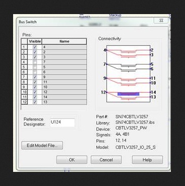
  • Richard,

    It appears if the customer changes the IBIS file as below, he should be able to connect pin12 to 13. As you can see, the functional_table_group by default is set to choose mapping between pin12 and 14. So here we are setting the functional_table_group value to “2”.  It’s a pain that one has to modify the file for a different set of mux path, but it is how the switch/mux is defined in the current IBIS specification. Hope this helps.

    Regards,

    -Eric Kim (WEBENCH Design Center)

     capture1.pdf

  • Eric,

    Thanks so much for your response!

    I will let you know if the customer has any further questions.

    Thanks again.

    Richard Elmquist

  • Eric,

    The customer ask some further questions:

    However I see this table has the 3.3V references commented out.

    Since I am using 3.3V should I change them to comment out “25” and un-comment “33”

    Why does this model not work with the bus switch GUI that is activated when I open it.?

    Maybe some model select statements or otherwise are needed?

    Please let me know if you have any questions for the customer.

    Thanks for your help with this!

    Richard Elmquist

  • Yes, please comment out the statement containing  CBTLV3257_IO_25_S and uncomment the one with  CBTLV3257_IO_33_S. I would like to verify it with the tool but I am having a tool license issue so unable to verify. I’ll try to at it as soon as the license issue is resolved. Please give it a try and let me know.  

    -Eric Kim (WEBENCH Design Center)

    pic1.pdf

  • Eric,

    Thanks for your help!

    I will let you know if this fixes the issue.

    Have a wonderful holiday season.

    Richard Elmquist