This thread has been locked.

If you have a related question, please click the "Ask a related question" button in the top right corner. The newly created question will be automatically linked to this question.

TINA/Spice/OPA188: output noise of OPA188&333 in same circuit

Part Number: OPA188
Other Parts Discussed in Thread: TINA-TI, , OPA333, OPA376, OPA191, OPA192

Tool/software: TINA-TI or Spice Models

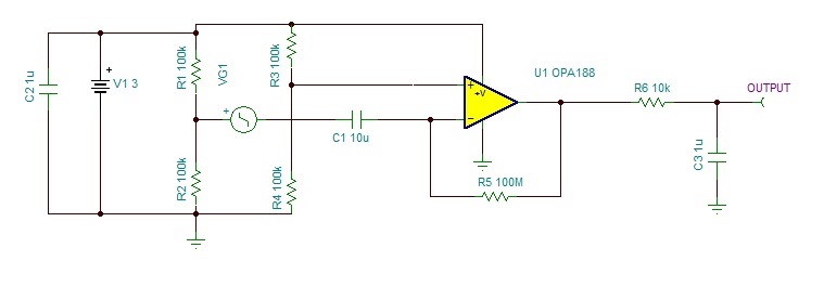
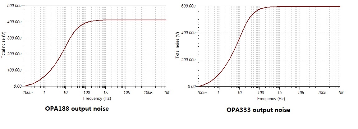
The output noise is very close when putting OPA333 and OPA188 in the following same circuit, why?  known that the RTI noise is 8nV/rtHz VS 55nV/rtHz in the spec.

BRs, JH

  • Hi JH L,

    It seems to me that the OPA188 modeled noise in TINA-TI is not accurate. The OPA333 modeled noise seems accurate. So, you can trust the plot for OPA333, but not the one for OPA188.

    Some comments:

    1. Decouple the bias that you're generating on the non-inverting input (R3, R4 junction) to ground with a shunt cap to reduce the thermal noise of those resistors contribution to output noise. This noise will overwhelm any contribution from the active device noise itself.

    2.The total supply voltage should be at least 4V minimum for OPA188 (whereas you have it as 3V).

    3. Make sure that the 100M feedback resistor you have in the circuit does not show any simulation instability (by running Transient and AC Analysis as well on your circuit).

    4. I believe you are showing the plots at each device output pin and not at the "OUTPUT" node of your circuit (which should have a 16Hz low pass characteristic due to R6, and C3). Please verify.

    Regards,

    Hooman

  • Dear Hooman,

    We build a real PCBA to test the circuit, found the output noise is around 20mVpp using the same circuit simulated in TINA while the simulated output noise is only 600uV x 6.6 =4mV with OPA333, there is big difference. We know that clean power supply to the bridged 4x100Kohm resistors is very important, so we use battery to power it like CR2032. The output noise captured can be lower to 12mV, but still triple of simulated output noise. We are sitll optimizing the circuit, that's great if you have any comments.

    To your comments.

    1, Adding a shut cap 100nF parrally with R4 does worse for the output noise from the actual test data. Maybe charge injection caused by this cap when using OPA333 chopping amplifier? I am not sure.

    2, we will adopt OPA333,not OPA188.

    3, yes, we checked it. Luckly no rings.

    4, the output noise simulated is at the "OUTPUT".

    At last,  your comments "the thermal noise of those resistors contribution to output noise. This noise will overwhelm any contribution from the active device noise itself." confuse us. We know that 1Kohm resistor has around 4nV/rtHz noise density, so R3||R4 give a 50Kohm source resistance, then its noise density is 4 x SQRT(50) =29nV/rtHz, it is only around half of OPA333 input voltage noise 55nV/rtHz.   But if 55nV/rtHz is the dominant contribution to output noise,  the simulated output noise 4mVpp is far from the real test data 12mV.   Do you see any possible cause?

    Thanks , JH

  • Hi JH L,

    When you measure the 20mVpp at the OUTPUT (instead of expected / simulated 4mVpp), what is your "source" set to? Is it in-circuit or have you shorted across it? The reason I ask is to eliminate any inherent random noise that your source might be generating?

    In this simulation, you've used an ideal source (0ohm series resistance). How close is that to the real source you are using? Any source resistance (assuming it is comparable to about 50kohm) will have an impact on noise, in addition to any inherent noise it may generate.

    You are correct that 50k noise is lower than the OPA333 input referred voltage noise, but it is still a measurable component of overall noise. I'm puzzled why decoupling the bias makes the circuit noise higher!

    What about the 100M resistor in the feedback. Do you have any datasheet / spec to share about that resistor? Some high value resistor constructs are noisier than others. I'm referring to whether it is carbon compound, metal film, glass, etc.

    I've simulated your circuit and get the same TINA-TI simulation results that you are getting. The dominant noise source is the OPA333 input referred noise voltage gained up by the closed loop gain of about 2,000 V/V (100M / 50k) resulting in 110uV/RtHz which translates to about 1.2mV_RMS over ~100Hz at "device output pin" (which matches simulation).

    I don't have a clear cut opinion / answer as to what your issue might be. Hopefully other people on this forum may have ideas to chime in?

    Please let me know about my query above related to your source characteristics.

    Regards,

    Hooman


  • Hi Hooman,

    In my real board, there is no "Source" like VGA1 showing in TINA. Only 4 x 100Kohm metal film resistor to work as a equivalent bridge sensor, I think this is ok to check the board noise. 

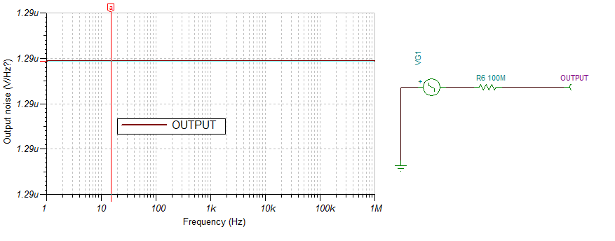
    By the following simple simulaiton, TINA has exactly included the resistor noise.  The 100Mohm resistor working as Rf, it should be neglected when calculating AC noise since it is parallel with R1||R2(50Ohm), the input serial cap C1 working as shorted for AC noise.  The onboard 100Mohm resistor is metal film.

    So the total dominant RTI noise is around to  SQRT( ( 4nV/rtHz x SQRT(50))^2 + ( 4nV/rtHz x SQRT(50))^2 + (55nV/rt/Hz)^2) = 68nV/rtHz.  the output noise is 68 x 2000 x SQRT(16x1.57)  x 6.6= 4.5mVpp, there is still big gap from my real board test.  have used battery to power the board, no obvious improvement.

    I am not quite sure how the input serial cap 10uF affect the noise in the circuit, especially working with a 100Mohm feedback resistor.  Can it  be simply neglect?  Seems TINA does neglect it.   Is there any article discussed the similar application?

    Appreciated any feedback. 

    BRs

    JH

  • Hi,

    After more investigation on the real board, found the thermal noise of 100Mohm feedback resistor can be neglect in my circuit, TINA's simulation result is definitely correct -:)

    The root cause of heavy noise may probably comes from the noise of power supply to "bridged sensor" on my board. What confused me is why the output noise have no obvious reduction when using battery like CR2032 to power the "sensor".

    Refer to the public paper "measurement of voltage noise in chemical batteries" test result, almost all kinds of batteries have much lower noise data than the active integrated chip power source. Does anyone have any comments here? thanks.

    BRs
    JH
  • JH,
    You may NOT use chopper amplifiers like OPA333 or OPA188 with a bridge sensor input in the noise sensitive applications because the chopping front-end of this class of amplifiers intruduces a short duration (few nono-second) input bias, IB, current spikes with the magnitude of up to 100nA. Therefore, in your application, these IB spikes get converted into voltage spikes (Vpp=100nA*100k=10mV) across your bridge resistors adding to the overall noise.
    For bridge sensor precision applications please use linear op amps (not auto-zero): low supply voltage OPA376 (Vss_max=5.5V) or either OPA191 or OPA192 for higher supply voltage (Vss_max=36V).