This thread has been locked.

If you have a related question, please click the "Ask a related question" button in the top right corner. The newly created question will be automatically linked to this question.

TINA/Spice/LP5907: ground current does not work

Part Number: LP5907
Other Parts Discussed in Thread: TINA-TI, , ATL431

Tool/software: TINA-TI or Spice Models

Hi,

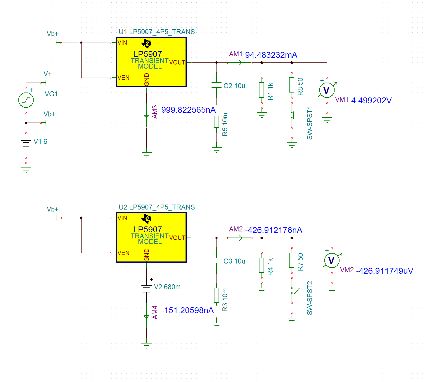
  I found that GND pin current of LP5907 model is always 1 uA, doesn't change with load current as shown in the datasheet.

Furthermore if I raise GND pin from ckt ground with 680 mV battery, the LDO doesn't start, output is a false -0.5 mV.

I wanted to convert 4.5V chip into a 5.2V LDO by adding a biased diode between circuit ground and GND pin,

biased by a resistor from Vin or Vout whichever gives the best line load requlation.

Please find attached .dsn file. I run the latest TINA sw from Designsoft on Win 7 64bit.

Can you suggest a solution to sym this application of this LDO? I looked for this LDO type becasuse it has

the best noise data and price.

Best regards, Endre

LP5907-Iq-error.TSC

  • hi Endre,

    unfortunately I can't open the file (seems corrupted, can't say)...
    anyway, aren't the data in Figure 5 of the datasheet enough for your purpose?

    KR
    Vincenzo
  • Hi Vincenzo,

      thanks for the quick response ! The file was exported from the latest TINA V11, please find attached a simplified version in V9,

    or see the attached picture.

      My goal was to simulate if I can raise the output voltage of the part by adding a diode in the ground connection. I couldn't simulate

    this and found that GND current is not simulated properly . I thought that the two problem is coupled and raised this thread to inform you.

      What I really want is to have a LP5907 with 5.2 Vdc out running from 6Vdc in, with simulated performance. Application is to feed some

    audio DAC chips with low noise supply. And want to stay in the <0.2 USD budget per rails.

    BRG, Endre

    LP5907-Iq-v9.TSC

  • Hi,

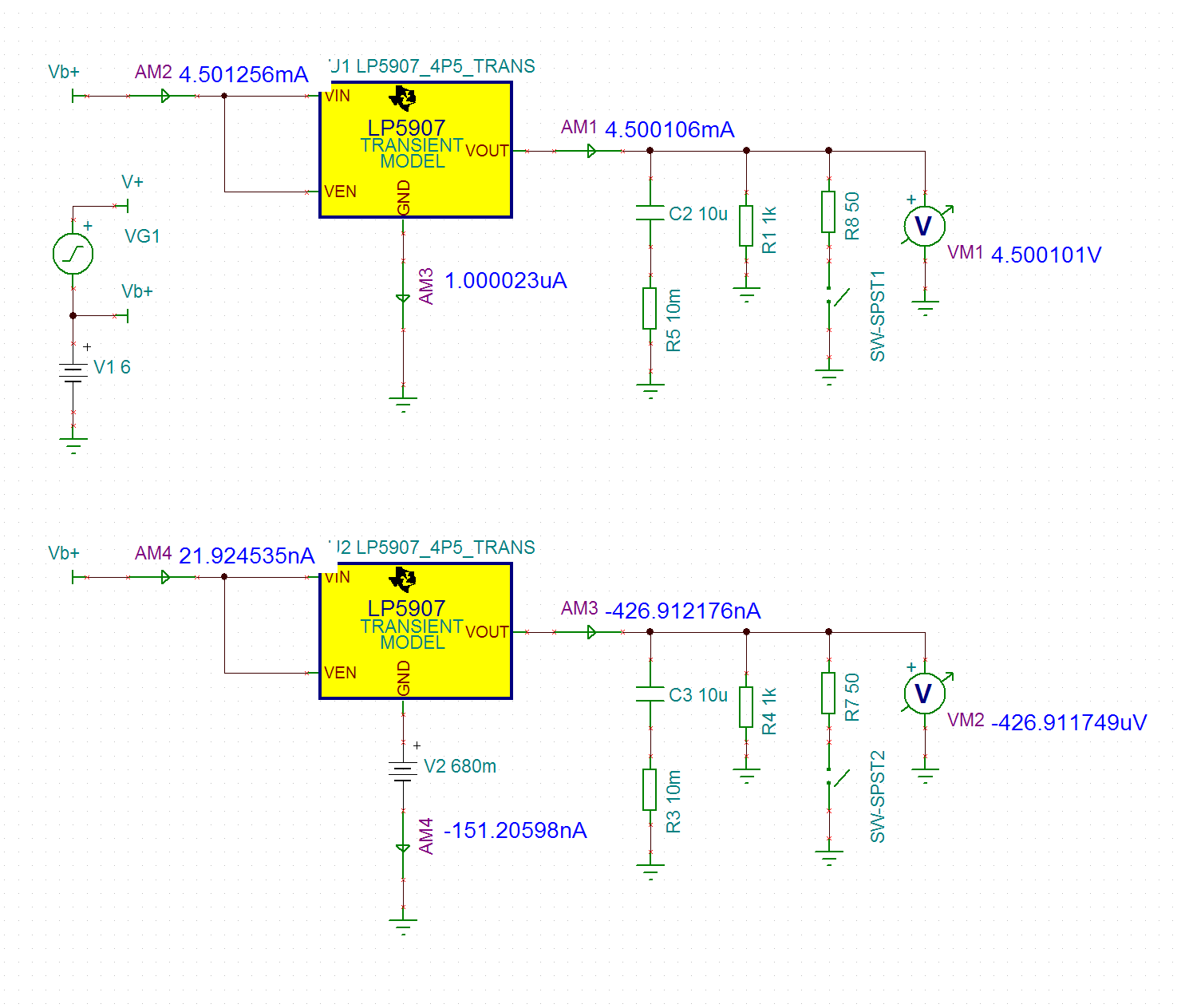
      just wanted to add that maybe the problem is that this SPICE model somehow references the global ckt ground directly, not

    only via the GND pin. The picture below shows that the sum of the Vin, Vout and GND pin currents are not zero in neither cases.

    I cannot debug this further, the model is encripted.

  • endre,

    A couple of things to note about the LDO model. The ground and input currents are not modeled in the device. The model is purely behavioral and the analog behavioral blocks used do not model the current dependencies in the circuit. Also, as you noted, the model has built in connections to ground in the model equations that will not allow you to offset ground and have that offset reflected accurately in the device performance. This is due to the architecture we have chosen to simplify the model for the LDO devices.

    You might want to make a follow-up post to the Linear Regulators forum to see how load/line regulation would be effected with the diode addition to ground. The model in this case will not give you the information you desire.

  • Hi Britt,

    thanks the quick response ! I understand the limitations in the model. I think if there is no quick & easy fix to this problem than it is easier to make a real measurement on it then to create more typing :)

    brg, Endre
  • Endre,

    Understood. Thanks for your interest in TI parts.

  • hi Endre,

    ok understood now...
    well, I won't recommend this approach for a couple of reasons:
    a) the diode will introduce noise directly on the VOUT
    b) the regulation of the VOUT will be lost because of the spread of the VF of the diode vs IGND, that will drastically change w/ temp. and IOUT...
    if you are concerning about noise then I would consider another part (like the LP2985-50) or, as acceptable tradeoff (assuming the IGND is always >20uA / see fig.5), I would consider using an ATL431 in place of the diode: this will shift the VOUT by a fixed and precise 1.24V
    last but not least consider addding a small ferrite at the input supply line to improve the PSRR performance at HF

    KR
    Vincenzo

  • Hi Vincenzo,

       thanks for the ideas, but wouldn't ATL431 enter way more noise than a diode, just based on datasheet Fig 9?

    I would not mind the temperatutre drift of a simple diode or two, app is 0..40C commercial audio.

    Actually the thing is not that so simple like you say. A diode can even improove line regulation when biased properly

    from the output side. Increasing load will drop LP.VOUT - LP.GND voltage, but create higher LP.GND current thus 

    increase diode voltage which can compansate for the LP drop. Only issue is that diode can change more than LP drop,

    finally creating negativ output resistance. So diode shall be put into a poroperly biased state. And maybe a C somewhere 

    to correct phase if neeed.

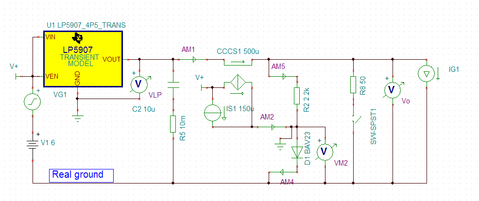
      Do you think that the attached ckt arrangement can properly simulate what I want? I introduced a new 'Real ground' and

    moved other components to this. And added IS1, CCCS1 to simulate LP.GND current with Io/2000 + 150 uA.

      It seems to work and shows PSSR is unchanged, but line regulation improoved by a factor of 3.

    Brg, Endre

  • cool, yes that solves your problem!
    nice idea :)