This thread has been locked.

If you have a related question, please click the "Ask a related question" button in the top right corner. The newly created question will be automatically linked to this question.

TINA/Spice/LM5017: Convergence error in simulation: UVLO and VCC pin settings

Part Number: LM5017
Other Parts Discussed in Thread: TINA-TI,

Tool/software: TINA-TI or Spice Models

Hi,

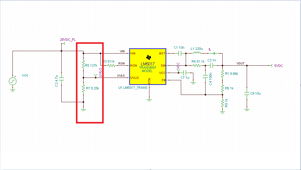
I am using LM5017 switching regulator and doing transient analysis on it.
Please refer the attached circuit.

Problem:
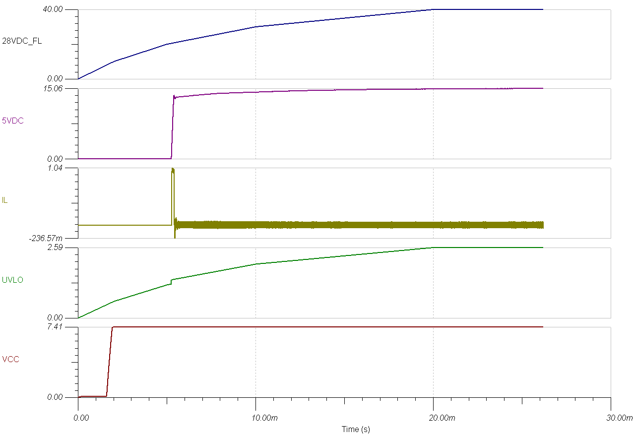
when the input voltage exceeds ~29.5V, tool is throwing a convergence error.
conditions are:

RUV2  5.11E+04 ohm
RUV1  1.00E+04 ohm
Vout  28  V
UVLO pin 4.58  V

and I_Hys 2.00E-05 A  {Vin(Hys) = I_Hys * RUV2}
Vin (Hys) 1.02  V
  
V_IN(UVLO, rising) = 1.225V * [(RUV2/RUV1) +1] = 7.48475 V

Please help me to understand the role of Vin(Hys) and V_IN (UVLO, rising) voltages and
and why is convergence error ocurring the moment UVLO pin voltage is reaching ~5V.

Sunney

LM5017_transient_ana.TSC

  • Hi Sunney,

    I am looking into this issue and it seems that there is some issue with model. I will try to get back to you on this by 03JAN2018.

    Below is the description from Datasheet about UVLO.

    There are two threshold for UVLO, one is rising and one is falling which helps to decide low current shutdown mode and standby mode. IHYS current is used to generate UVLO hysteresis.

    Thank you for your patience!

    Regards,

    Saket

  • Ok Saket. I will wait for your response.

    Sunney

  • Hi Sunney,

    I looked into model and the way the UVLO functionality is implemented we cannot apply a voltage more than 5V at UVLO pin and that is the reason you are getting a convergence error when UVLO voltage is near 5V.

    I tried to simulate your setup with different value of resistor divider (which keeps the voltage at UVLO pin well below 5V) and then I didn't see convergence issue.

    PFA modified TINA tsc file, schematic and simulation results.

    2625.LM5017_transient_ana.TSC


    Please let me know if you have other questions.

    Thanks & Regards,

    Saket

  • Hi Saket,

    As per datasheet, the UVLO pin to RTN can be between "–0.3V to 100 V".

    I have attached another schematic where UVLO pin is at ~14V and the circuit is running fine.

    Please look in to the model and let me know if you can provide the updated one.

    Sunney

    LM5017_ana.TSC

  • Hi Sunney,

    I simulated the attached tsc with the ramping voltage source and I got the same convergence issue as you were getting initially.TINA model is able to converge the model with DC voltage source but not with a ramp or unit step sources.

    There seem to be issue with the way UVLO is implemented in model and we need to check and fix the model.
    That can take 1-2 week's time and we will upload the revised model on web.

    Meanwhile, (as a temporary fix) you can keep UVLO node voltage below 5V (by choosing appropriate resistor divider ) and use the model for checking features other than UVLO.

    Thanks & Regards,
    Saket
  • Hi Sunney,

    We have updated the UVLO isue in the Pspice and TINA models on web. Please find them at   

    Please let me know if anything else is needed from our end.

    Thanks & Regards,

    Abhisek

  • Hi Abhishek/Saket,

    Thank you for all your support. The model is working fine now.

    Sunney