Other Parts Discussed in Thread: TINA-TI,
Tool/software: TINA-TI or Spice Models
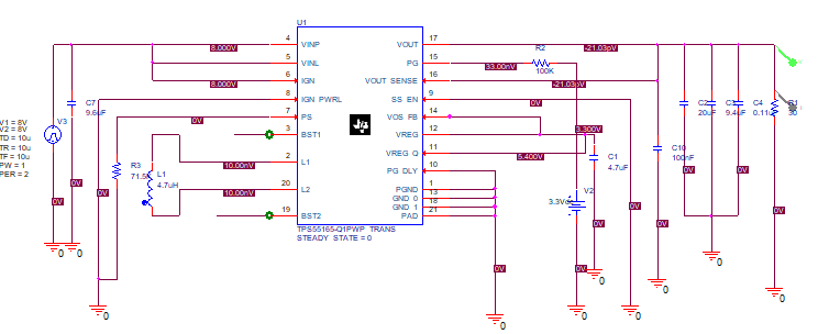
I am trying to simulate TPS55165-Q1 in fixed 12V output in pspice, when I try to connect BST1/BST2 to cap as recommended in the datasheet, I get an error saying the pin is floating , I have tried running in multiple machines but the issue remains same, Please see the screenshot below,
SETUP:
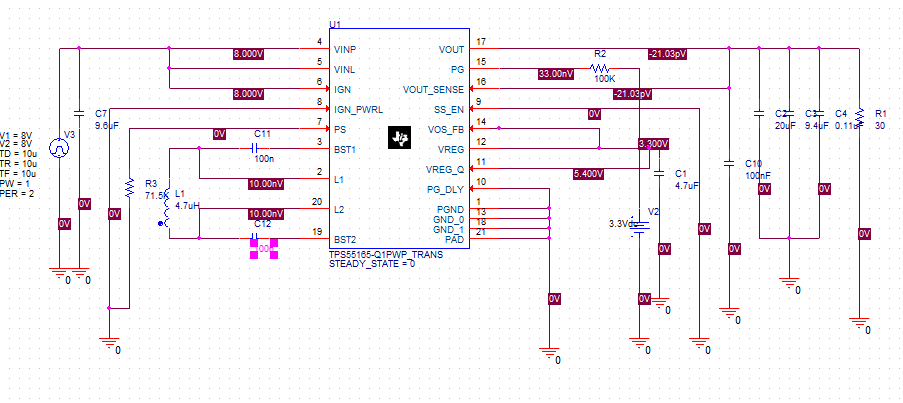
Error:

N03722 is the node name for the wire connected to BST1, N03726 is for BST2.
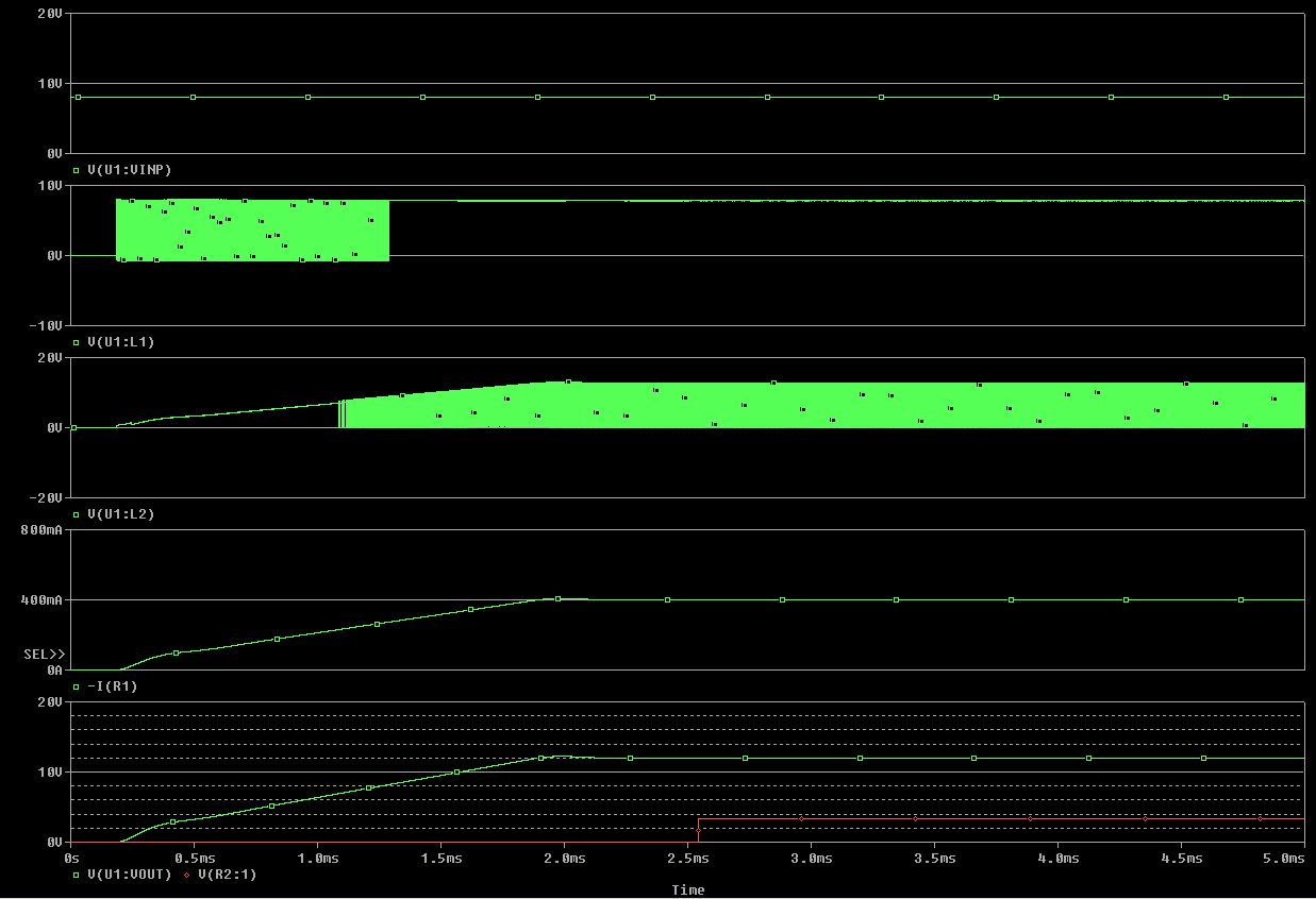
When I try to connect it without cap, it works fine till 3ms and output travel back in time at 12V constant. i.e., out is 12V like I want but in time 3ms-0ms,which shouldn’t be possible. I have attached project files fyr.