This thread has been locked.

If you have a related question, please click the "Ask a related question" button in the top right corner. The newly created question will be automatically linked to this question.

TINA/Spice/INA240: Noise problem appears with high current shunt on INA240 output

Part Number: INA240
Other Parts Discussed in Thread: TINA-TI, ADS131A04,

Tool/software: TINA-TI or Spice Models

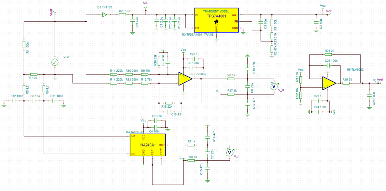
We start a schematic to measure high current on low voltage systems, 48V battery powered system to be precise. The current will be measured with a shunt, up to 5000A. The used shunt is 10uOhm located on the negative connection of the battery and it is connected to the INA240A1. On the output will be an A/D converter, the ADS131A04, 24bits Sigma/Delta.

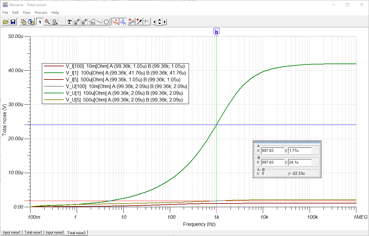
The simulation gives results as expected, except on the noise analysis. It shows us that when the shunt resistance goes low to the real value, 10uOhm the noise rise 10 time higher than wanted for the AD converter. The same simulation with a 500uOhm shunt show a noise 20 times lower than before. 

The stage is filtered at entry at 1.5kHz 1 order and at output also a filter stage of 1.5kHz 1 order. 

The simulated noise level are :

1.77uV @1kHz with 500u shunt

24.1uV @1kHz with 100u or 10u shunt.

To use the ADC correctly the noise level should not be higher than 2.8uV.

Are the results correct or did I made errors on the use of TINA simulator ?

What causes this moise rise and how can I avoid it ? 

I have all files if needed...

Best regards, Philippe

  • Hello Philippe,

    Could you please share the schematic files. It will help us to debug the discussed issue.

    Best Regards,
    Aditya
  • Sorry, I made a mistake on the file load...

    BmsNewHF.TSC

  • Phillipe,

    In the uploaded schematic, it looks like the jumper J1 is not connected to the INA240 REF1/2 pin connection.
    Could you check that on your schematic?

    Once you have confirmed that is okay, could you check the INA240 input and output DC voltages to confirm they are what you expect?
    In the uploaded schematic, the INA240 DC output is very close to the positive rail.
    It may be the INA240 bias point is compressing the output and that's throwing off the noise sims.

    Regards,
    John

  • Hello, 

    I made a check of the above remarks :

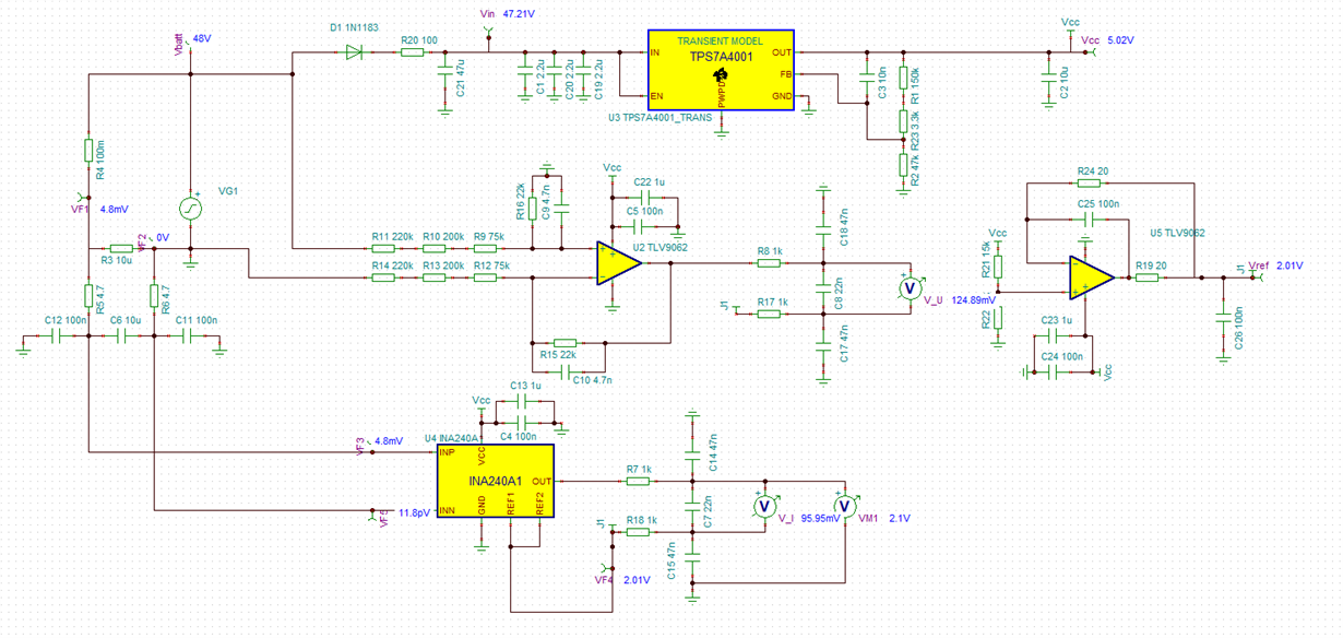
    - J1 is connected, it can be seen at the DC analysis, below.

    - 48V / 0.1 = 480A, UIna = 480 * 0.00001 = 4.8mV, Correct voltage are présent.

    - The output of the INA is actually at 2.1V, really near of the mid voltage of the power supply, so not near from the rail.

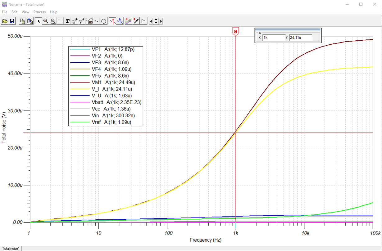
    and the noise analysis is identical.

    Thanks for the ideas !

    Regards,

    Philippe

  • Phillipe,
    If the noise behavior is still not what you expect, would you please upload the latest schematic to this thread.
    The last one did not show the same results, even after correcting the J1 connection.
    Regards,
    John
  • Hello,

    The noise level is too high, the goal is 2.9uVrms.

    I made a simulation wiht the file that is attached and the noise result is equal :

    BmsNewHF - autosave 17-12-28 14_39.TSC

    I did not made any changes, strange that the behaviour has changed. 

    Above is first the noise simulation from the same schematic, and after the TINA schematic file, .TSC.

    Regards

    Philippe

  • Philippe,

    The reason the noise is lower with the 500u shunt is because the resulting input voltage (with the 48V source) is driving the output of the INA240A1 into saturation (~4.97V). This causes the device/model into a nonlinear mode of operation, and because of this, the noise looks lower.
    As an experiment, reducing the DC voltage of the signal source  48V to 12V, causes the INA240A1 DC output to fall from 4.97V to 3.19V. This in turn causes the model to shift its operation to the linear range of operation. As a result, noise to increases from 1.36uVrms to 24.52uVrms.

    With the nominal source (48V) and the smaller (10u) shunt, the model's DC output is equal to the Vref (2.1V) so the model remains in the linear mode of operation, and the noise is the expected value: 24.52uVrms.

    You can confirm the simulated noise performance with a simple calculation.
    The INA240 input referred noise is 40 nV/rt(Hz), and the gain of the INA240A1 is 20 V/V.
    The input-referred noise for this device is constant from DC to about 100kHz.
    In this case, the input resistors are small, so their noise contributions are negligible.
    So we can approximate the total output noise from DC to 1kHz as:
    Vo,noise = Vi,n * Gain * sqrt(1kHz) = (40nV/rt(Hz))*(20V/V)*(31.62 rt(Hz)) = 25.3 uVrms

    This simple calculated result is very close to the simulated value, so it looks like the model and simulator are okay.

    You mentioned the goal for noise is is 2.9uVrms. We can use the calculation above to estimate the required device noise.
    If we assume the needed gain is 20 V/V and the bandwidth is 1kHz, then the required device noise can be estimated as:
    Vi,n = Vo,noise/(Gain*sqrt(1kHz)) = 2.9uVrms/(20 * 31.62) = 4.6 nV/rt(Hz)

    I hope this helps. Please let me know if you have any questions.
    Also, if you would like help finding a device that will meet your goals, I can transfer this thread to the E2E forum that is supported by the product experts. Please let me know if that is what you would like to do. 

    Regards,
    John

  • Dear John, 

    Thanks for the explanation, I understand the case now. I will do different simulation now and we will see if we keep this part or or loocking to one with less noise...

    Best Regards

    Philippe