This thread has been locked.

If you have a related question, please click the "Ask a related question" button in the top right corner. The newly created question will be automatically linked to this question.

TINA/Spice/FILTERPRO: TINA/Spice/FILTERPRO

Part Number: FILTERPRO

Tool/software: TINA-TI or Spice Models

HI :

   I used"filterpro" to design a high pass filter,  i choosed the "Mutiple Feedback ftilter", then i used TINA to simulation, and i found the result is  related to the source resistor, and then i verify the result on the board, i want to ask how can i solve the problem? can you provide a good method?  by the way , the op-amp is "ADA4841"

   thanks for your reply!

  • If i understand your question: basically you're asking why your high pass response changes with the source resistance.. am I correct?

    This is because we're assuming source resistance = 0 ohms as the voltage generator stimulus. To be able do this, you have to drive the high pass circuit with low impedance source. For instance, on simulation you can insert VCVS in between the voltage generator and the HPF circuit as to isolate the impact of your source resisance:

    Voltage Generator + VCVS (Gain of 1x) + HPF Active Cricuit.

    In real life/board/lab measurement, you can replace VCVS (Gain of 1x) with opamp at unity gain configuration.

  • thanks for you reply!

    yes,you are correct.

    following your method, i do the exercise.

    and i have some questions as follows:

    1.i use the ADA4841 with unity gain configruarion to simulation. if i configured the resource resistor "1MEG ohms", the transfer function is the state of attenuation.

    2. some opamp with unity gain configuration easily  selfly excitate, if i concerned the low noise and low consumption, can you give me a recommendation about the unit gain opamp.

    thank you again!

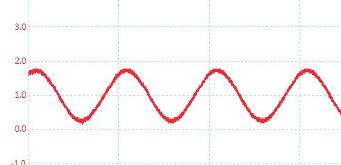
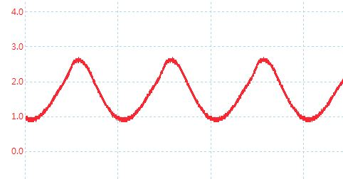
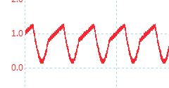
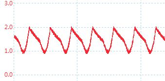
  • this afternoon, i used the ADA4841-2 to do the test,one opamp in ADA4841-2 is used for the unity gain configuration, and the other is uesd for high pass filter, the amplitude of the source is 760mv with DC voltage is 1V,

    the two exercise "1.the frequency  is 500Hz,  and 2. the frequency  is 3KHz, the results are as  follows:

    i want to ask the reason of the result ,thank You!

    500Hz

    Output of the unity gain opamp


    Output of the high pass fiter


     3KHZ

    Output of the unity gain opamp


    Output of the high pass fiter


    The schematic


  • thank you ! please see my new problem!
  • What's the f-3dB of HPF you're trying to design?

    Also, can you attach your .TSC file or TINA file into this post so that I can take a look what's happening?
  • Hi In ye,

    Jut want to follow up with you on this. Let us know if you still need our help on this. If you do, could you please answer the question I posted last week so that I can further help you.

    If I don't hear from you within a week, I will assume that you somehow have already resolved this issue, and I will be closing this post.

    Herman
  • unitgain+MFB HPF.TSCi'm so sorry for the delay because of the vacation in recent time.

    f-3dB of HPF is 1HZ.

  • hi:

    can you give me more suggestion about the problem,thank you!

  • Hi,

    I am still looking into this. I am not 100% sure yet why it gives such result.

    Herman

  • hi herman:

    thank you, actually, the simulation result can also show the problem!

  • Hi In ye,

    I noticed that if you sweep the frequency response / bode plot beyond 10kHz and up to 1MHz, you'll notice there is high resonant around 65kHz. I think that's what's causing it.

    I would recommend not to use Multiple-Feedback (MFB) Architecture rather use Sallen-Key (SK) Architecture instead. I think MFB is pretty sensitive to resonant as the feedback components (Resistors and Capacitors) interact with the output impedance of an amplifier.

    Also as far as TI part, you can use OPA836.

    You can also go to www.ti.com/.../products.html to search for the opamps that meet your requirements.

    Herman
  • Hi In ye,

    I noticed that if you sweep the frequency response / bode plot beyond 10kHz and up to 1MHz, you'll notice there is high resonant around 65kHz. I think that's what's causing it.

    I would recommend not to use Multiple-Feedback (MFB) Architecture rather use Sallen-Key (SK) Architecture instead. I think MFB is pretty sensitive to resonant as the feedback components (Resistors and Capacitors) interact with the output impedance of an amplifier.

    Also as far as TI part, you can use OPA836.

    You can also go to www.ti.com/.../products.html to search for the opamps that meet your requirements.

    Herman
  • hi herman:

    thanks for your reply!

    can you tell me how to find the resonant frequency! i have no idea about that !

    i hope to verify whether the schemetic is stable before designing a real board!

  • In ye,

    You can follow the following steps:
    1. Open the .TSC or TINA file
    2. Click on Analysis -> AC Analysis -> AC Transfer Characteristic
    3. Alter the end frequency to "10M".
    4. Click "OK".
    5. Observe the graph that comes out of that.
  • thank you! i will verify another filter type as you said 

  • You're welcome. I am going to close this post/thread. If you further questions on the other filter type, please open up a fresh new post with different subject so that we can address it separately on that separate post.