This thread has been locked.

If you have a related question, please click the "Ask a related question" button in the top right corner. The newly created question will be automatically linked to this question.

LM25118 – About same circuit for multiple output

Guru 21045 points
Other Parts Discussed in Thread: LM25118

Hi,


My customer would like to use LM25118 at the following condition.


[Use condition]

Vin=10.8V to 15V

Vout is changed from 8.0V to 15V.

Iout=3.0A (max)


Therefore, they would like to simulate the case1 and case2 with the same design.

And, they would like to know the most suitable design common to both case1 and case2.

Please let me know if you have any advice.


-Case1 Vin=10.8V to 15V , Vout=8.0V , Iout=3.0A

-Case2 Vin=10.8V to 15V , Vout=15V , Iout=3.0A


Regards,

Kanemaru

  • Hi Kanemaru-san,

    WEBENCH gives a design for Case 1, but not Case 2 because of a design inputs check. If you change the VinMax to 15.01V, WEBENCH can bypass this check.

    I'll see if the product group has additional inputs for this design case.

  • Hi 

    My recommendation is to design a board based on Case 2 and then revisit  Rcomp, Ccomp, Ccomp2,  Rfbb, Rramp and Rsense values based on Case1 requirements. 

    Regards, 

  • Hi Kevin-san, Eric-san,


    Thank you for your prompt reply.

    I have the following question([Q1] and [Q2]).


    Is this operation of the Webench right?

    And, could you please improve this phenomenon?


    -------------

    [Q1]

    We can't simulate the case1.

    We confirmed the fault report which is mentioned about "VinMin is too low" and "Solution's function does not match design".

    However, when I changed the Vin(min)=10.8V to 10.6V, the simulation was carried out.


    *Please refer to attached file “Case1” and "Case2".

    0042.Case1 Vin=10.6V to 15V , Vout=8V , Iout=3.0A.pdf


    5873.Case2 Vin=10.6V to 15V , Vout=15V , Iout=3.0A.pdf

    -------------


    [Q2]

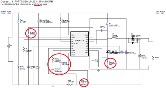
    I changed the following parameter according to your advice.

    (The input voltage of the case1 and case2 is "10.6V to 15V")


    However, I believe that this circuit can't be stable because the Phase Marg is -0.3deg.

    And, I changed the Rfbt=11.3kohm to 5.49kohm, but the output voltage was not changed.

    Please let me know your advice.


    <parameter>

    Rcomp : 44.2kohm -> 61.9kohm

    Ccomp : 560pF -> 270pF

    Ccomp2 : 4.7nF -> 2.2nF

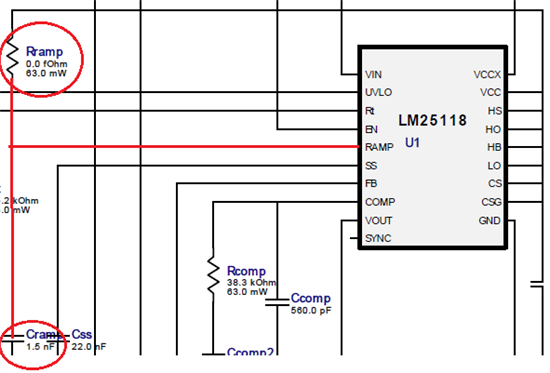
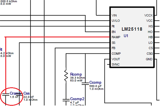
    Rramp : 280kohm -> 0ohm

    Rsense : 16mohm -> 20mohm

    Rfbt : 11.3kohm -> 5.49kohm

    (Rfbb is fixed at 1000hom)


    *Please refer to attached file “Case3”.

    4645.Case3 Vin=10.6V to 15V , Vout is changed from 15V to 8V , Iout=3.0A.pdf

    -------------


    Regards,

    Kanemaru

  • Hi Kanemaru,

    We will take a look at the design inputs for your Case #1 to debug.

    For Case #2, please note you can not force a change in Vout for a WEBENCH design by changing the Rfbt/Rfbb in the BOM. You have to create a new design to set a new Vout parameter. On the SPICE simulation, you can adjust the Vout.

  • Hi Kevin-san,


    Thank you always for your kind support!

    I have one more question.


    [Q3]

    We would like to know the phase margin at the Case1 which is based on the parameter of the case2.


    Therefore, We created a new design to set the Vout=8.0V(Case1).

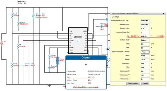
    However, I can't input the value which is based on the case2 to the Ccomp,Ccomp2,Rcomp,etc.

    Because there is the limit of the value.


    Could you please improve this phenomenon?

    I’d greatly appreciate your verification.


    <For example>

    We would like to input the Ccomp=560pF(This is a recommended value of case 2).

    However, we can’t input this value, because the range of the Ccomp is 620pF to 760pF.


    Regards,

    Kanemaru

  • Hi Kanemaru-san,

    You can still enter values for custom components that are outside the lower and upper limits. Click the "Save changes" and when the warning message comes up, click Ok.

  • Hi Kevin-san,


    I’m sorry for the delay in my reply.

    I performed this simulation.

    And, I would like to ask an additional question.


    [Q4]

    How do you decide a value of the Rramp?

    The calculation method of the Rramp is not mentioned in a datasheet.

    So, if we use same value at the case1 and the case2, we would like to know about your choice.


    <Case1>

    -Rramp is not connect.

    -Cramp is 270pF


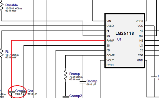
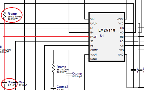
    <Case2>

    -Rramp is 280kΩ

    -Cramp is 1.5nF


    Regards,

    Kanemaru

  • Hi Kanemaru-san,

    The BOM calculator adds the Rramp resistor on the condition when the Vout is greater than 14, VinMin is greater than 7 and the estimated duty cycle for buck and boost mode are both greater than 45%.

    Rramp is calculated as Rramp = Vcc /(Vout * gm - Ioffset), where Vcc=7, gm=5e-6, Ioffset=50e-6

    This Rramp value is one of the parameters used to calculate the compensation components for the circuit. If no external Rramp component is used, then the calculator uses the value of 10e6 instead.

  • Hi Kevin-san,


    Thank you for the information.


    According to your advice, I believe that the Rcomp is not necessary if a phase margin is ensured.

    Therefore, I performed the simulation that I change the Rcomp =280kohm to 0ohm at the case2.


    <Case2 simulation>

    The phase margin is 36.15 deg.


    In addition, I changed the Cramp= 270pF to 1.5nF at the case1.

    So, I believe that I change the Cramp if a phase margin is ensured.


    <Case1 simulation>

    The phase margin is 46.455 deg.


    Is my understanding correct?

    I’d greatly appreciate your verification.


    Regards,

    Kanemaru

  • Hi Kanemaru-san,

    I agree with your verification and think the analysis is good. The next best step is to create the design on a PCB and test the performance to ensure design accuracy.

  • Hi Kevin-san,


    Thank you for your advice.

    I greatly appreciate your cooperation!

    We will report the simulation results to my customers.


    Regards,

    Kanemaru