This thread has been locked.

If you have a related question, please click the "Ask a related question" button in the top right corner. The newly created question will be automatically linked to this question.

Webench/UCC28911: UCC28911 calculation change documentation request

Part Number: UCC28911

Tool/software: Webench

Hi all,

I have an active design with the UCC28911 that uses design equations from the datasheet and leverages the WEBENCH model. I was informed on January 12th that there were issues with the equations and they've been corrected.  Can I please get a list of the addendum / errata so I can verify my development equations? Was the datasheet changed?

"

Updates made to the WEBENCH Design:

a. The Transformer Inductance calculation has been updated based on the desired set target switching frequency and the tool now supports improved core/bobbin selection with enhanced algorithm to give better transformer construction details(turns, AWGs, layers, strands, etc)

b. Rcs has been renamed to Ripk in the schematic and is re-calculated to set the value of Io(output current) in Constant Current mode with Dmagcc (secondary side conduction duty cycle) of 0.413

c. The preload resistor selection Rpreload has been made more accurate with the preload power sized so that it is higher than the Aux power

d. Advanced options for entering load transient is supported in the tool to help select appropriate Cout to fit in your application

e. The output preload resistor determines the converter minimum operating frequency. With the updated Rpreload value as mentioned in point c), Cout1 value will get automatically updated as well because the output capacitance is typically determined by transient response requirement from no load

f. Cvdd1 needs to supply device operating current until output reaches target minimum operating voltage in constant-current regulation. The time taken to do that depends on Cout. With an update in Cout( look at point e.), change in Cvdd1 value will also get reflected

g. With the update in Transformer Parameters(turns ratio, etc), we also encourage you to use the new values of snubber circuit comprising Dz, R3, C3, R4 , D1 along with the VS(voltage sense) pin resistors Rs1 and Rs2

"

Regards,

Aaron

  • Hi Aaron,
    There were no changes to the datasheet equations. The equations that are being used in WEBENCH calculations were updated to fix the issues with the components being selected. You can create a new design in WEBENCH and compare that with your existing design to see the differences in the components. The alert email that you have received also summarizes the possible components that you can expect to be changed. We recommend using the newer components recommended by WEBENCH.

    Regards,
    Gerold
  • Hi Gerold,

    Could you please give me more specifics?

  • Hi Aaron,

     Please find my responses:


    1. Rpreload equations are below and might require some iteration in some cases as shown at the end of the equation,  let me know if any question


    Rpreload_max = (Vout_Usr*Vout_Usr)/(VAUX*IAUX_MAX); VAUX = aux voltage, IAUX_MAX = max current drawn by aux at no load

    Rpreload_max = 0.88*Rpreload_max; // just a margin from the max value


    Numerator = ((VDD*IAUX_MAX) + ((Vout_Usr*Vout_Usr)/Rpreload_max));

    Denominator = ((L_pri*Ipeak_pri*Ipeak_pri)/(2*Kam*Kam)) - (0.07*Po/(Kam*Kam*IC_fsw_Act)) - ((Vf*Ipeak_pri*Ipeak_pri*L_pri)/(2*Kam*Kam*Vout_Usr));

     where,

    VDD = VAUX - daux.Vf_Act;

    IAUX_MAX = max current drawn by aux at no load

    L_pri = primary inductance

    Ipeak_pri = peak primary current

    Kam = 3.0

    Po = output power

    Vf = secondary side forward voltage drop

    IC_fsw_Act = switching frequency at full load

    fswmin = Numerator/Denominator; fswmin = min switching freq at no load

     if(fswmin<=fsw_min)    // fsw_min = 420 Hz, incase the calculated frequency goes below the converter minimum switching frequency, run a loop to increase fswmin and recalculate Rrpreload in reverse


    {

                  do

                  {

                  fswmin =fswmin*1.2;


                  Rpreload_max = (Vout_Usr*Vout_Usr)/((((L_pri*Ipeak_pri*Ipeak_pri)/(2*Kam*Kam))*fswmin) - ((VDD*IAUX_MAX)) - (0.07*Po*fswmin/(Kam*Kam*IC_fsw_Act)) - (((Vf*Ipeak_pri*Ipeak_pri*L_pri)/(2*Kam*Kam*Vout_Usr))*fswmin));


                  count++;

                  } while((Rpreload_max<=0 || Rpreload_max>(Vout_Usr*Vout_Usr)/(VAUX*IAUX_MAX)) && count<=2000);

                Rpreload ~ Rpreload_max;

    }


    else if(fswmin>fsw_min)


    {

                  Rpreload ~ Rpreload_max;


    }     


    2. Cout1 calculations


    Cout1_min = |(Io2entered-Io1entered)| / (fswmin * Vdeltaentered);                  


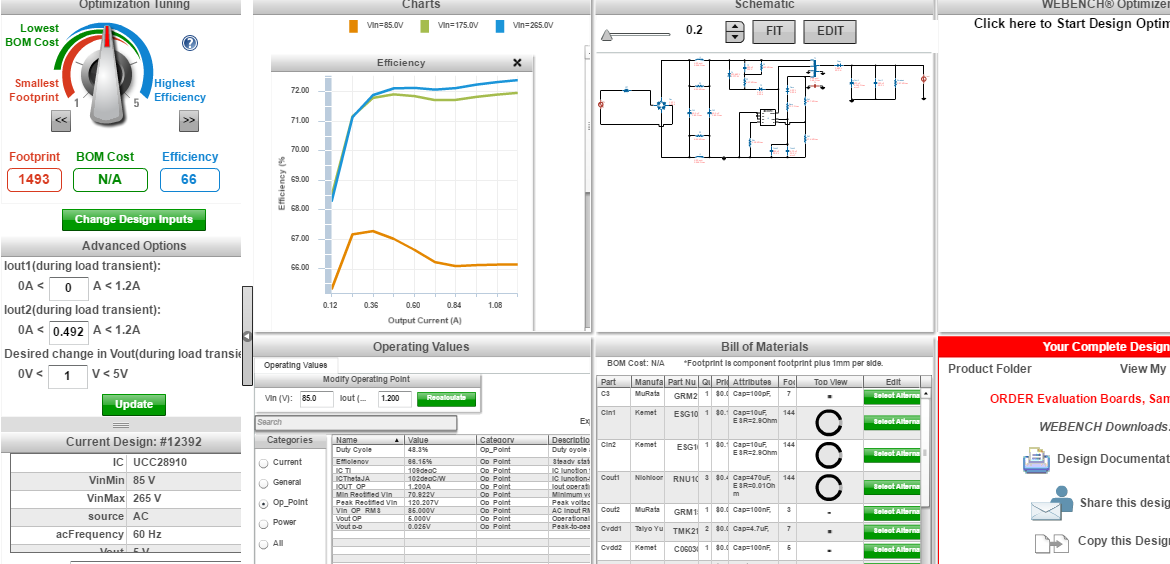
    You can enter Io2, Io1 and Vdeltaentered by using the advanced options on the left side of the dashboard window. I am attaching a snapshot for your reference


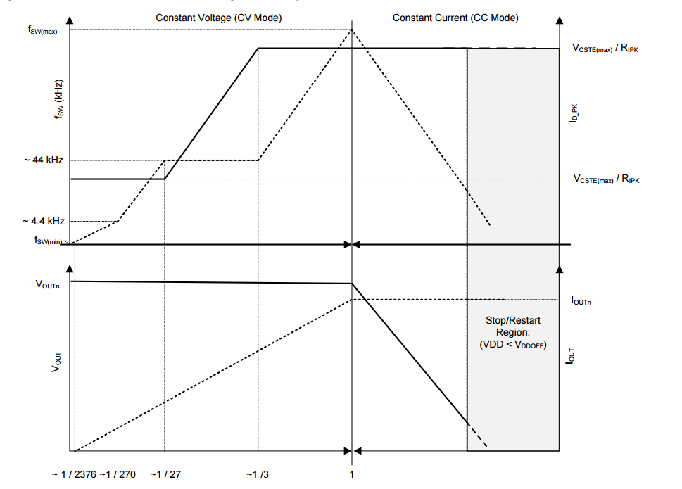
    // as this device works in FM mode as well from 0 to Iout, the fswmin in above equation should correspond to fsw of the device at min(Io1entered,Io2entered), to be determined from control law curve


    // one another eqn for compensation from datasheet


    Cout1_ds = (400*Iout_Usr)/(Vout_Usr*IC_fsw_Act)); // from datasheet- minimum Cout necessary


    Cout1_min = Math.max(Cout1_min, Cout1_ds);  // min value for Cout required

    // after this you can take some margin as required

    // for this device in WEBENCH , these are the margins taken

    Cout1_tgt = Cout1_min * 1.5;  // just taking some margin for the target value of Cout1 in WEBENCH

    Cout1_max = Cout1_min * 2


    You can see these limits by clicking on Cout1 in the schematic and then press Select Alternate Component, and then see what minimum values you can use for Cout1, then also prefer to chose your own Cout accordingly


    3. Cvdd equation


    Cvdd_min = (cout1*Vout_min*IC_supply_current) / (Iout_Usr*(UVLO_start_MAX - UVLO_stop_MAX));


    Vout_min = Math.max(Vout_Usr - 3.0,2.0);  // target lowest converter output voltage in CC regulation ,


    Let me know for any question,


    Thanks

    sahil