This thread has been locked.

If you have a related question, please click the "Ask a related question" button in the top right corner. The newly created question will be automatically linked to this question.

Linux/DLPDLCR2000EVM: Integration of raspberry pi zero video to evm

Part Number: DLPDLCR2000EVM

Tool/software: Linux

Hi , 

 I am trying to interface the DLPDLCR2000EVM module to raspberry pi zero  following the thread(http://e2e.ti.com/support/dlp__mems_micro-electro-mechanical_systems/video_and_data_display/f/947/t/651931)  .  I am able to detect the evm using i2cdetect  . However  I am unable to  switch the input source using sudo i2cset -y 3 0x1b 0x0b 0x00 0x00 0x00 0x00 i , nothing happens when i send this command , I have tried to follow  section 2.4.1.5 in the programmers guide  to change the  pixel data format to rgb666 using 

sudo i2cset -y 3 0x1b 0x0d 0x00 0x00 0x00 0x01 i  

but nothing happens still , could someone please help me locate my mistake , thanks 

I am powering the pi with a 5v/2A external adapter and the evm with a external 5v/3a adapter .

here is my boot/config.txt

# Uncomment some or all of these to enable the optional hardware interfaces

dtparam=i2c_arm=off

dtparam=spi=off

#dtparam=i2s=on

#dtparam=spi=on

# Uncomment this to enable the lirc-rpi module

#dtoverlay=lirc-rpi

# Additional overlays and parameters are documented /boot/overlays/README

# Enable audio (loads snd_bcm2835)

dtparam=audio=on

# NOOBS Auto-generated Settings:

# hdmi_force_hotplug=1

start_x=1

gpu_mem=128

# Add support for software i2c on gpio pins

dtoverlay=i2c-gpio,i2c_gpio_sda=23,i2c_gpio_scl=24,i2c_gpio_delay_us=2

# DPI Video Setup

dtoverlay=dpi18

overscan_left=0

overscan_right=0overscan_top=0

overscan_bottom=0

framebuffer_width=854

framebuffer_height=480

enable_dpi_lcd=1

display_default_lcd=1

dpi_group=2

dpi_mode=87

dpi_output_format=458773

hdmi_timings=854 0 14 4 12 480 0 2 3 9 0 0 0 60 0 32000000 3

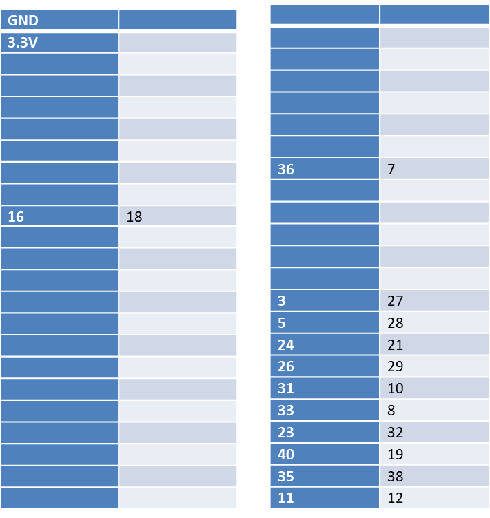
 and here are my connections  from evm  to the raspberry pi zero pin numbers .


Thank you .

  • Sripathi,

    Thanks for your interest in our DLP products.

    I have a couple of suggestions for you. First, have you tried communicating with the EVM to perform tasks outside of switching to external video? It appears you are issuing your I2C commands properly so it may be a different issue. For example, you can try switching from splash screen to internal test pattern after switching to RGB666:

    RGB666 >> i2cset -y 3 0x1b 0x0d 0x00 0x00 0x00 0x01 i
    Test Pattern Mode >> i2cset -y 3 0x1b 0x0b 0x00 0x00 0x00 0x01 i
    Grey Ramp Select >> i2cset -y 3 0x1b 0x11 0x00 0x00 0x00 0x0C i

    If the above works, there may be an issue with the way your Raspberry Pi's video pin mapping has been set up. If that is the case, I recommend you review your overlay configuration in Linux.

    I hope this helps.

    Best Regards,
    Philippe Dollo
  • Hello,

    I updated my guide at https://e2e.ti.com/support/dlp__mems_micro-electro-mechanical_systems/video_and_data_display/f/947/t/651931 to add my full pinout from the Raspberry Pi to P1 and P2 of the EVM module. Note that you don't connect the 3.3V on P2. Also make sure you have the EXT_SDA and EXT_SCL the correct way around.

    For the I2C tests you should only need the 3 connections of GND, EXT_SDA and EXT_SCL which should enable you to switch to the internally generated graphics test mode on the DLPDLCR2000EVM.

    My connections are by 20cm Dupont connectors and I didn't use any pull-up resistors for the I2C . The original I2C pin mappings for hardware I2C on the Raspberry Pi has relevant pullups added to the circuitry and I'm not sure if they are configured using internal pull-ups or not on the new pin mapping. If you have a long wiring connection, it might be a reason your I2C is not communicating, either try short connections for I2C or add 1.8k pullup resistors on the Raspberry Pi for the physical Pins 16 and 18). Hopefully it's just a simple wiring issue.

  • Hi philip ,
    thank you for the detailed guide ,

    my i2c is working fine all these commands are working
    RGB666 >> i2cset -y 3 0x1b 0x0d 0x00 0x00 0x00 0x01 i
    Test Pattern Mode >> i2cset -y 3 0x1b 0x0b 0x00 0x00 0x00 0x01 i
    Grey Ramp Select >> i2cset -y 3 0x1b 0x11 0x00 0x00 0x00 0x0C i
    sudo i2cset -y 3 0x1b 0x0c 0x00 0x00 0x00 0x13 i
    sudo i2cset -y 3 0x1b 0x0c 0x00 0x00 0x00 0x19 i (for 854 * 480)

    but
    sudo i2cset -y 3 0x1b 0x0b 0x00 0x00 0x00 0x00 i is not working ,


    All connections are same and I have removed the 3.3v connection as you suggested and modified the boot/config.txt as per the guide . Can you please tell me from the guide , what you meant by "provided you don't power cycle the DLPDLCR2000EVM, you'll be able to re-boot the Pi without affecting the picture" ? and are you working on pi zero w ? I am working with a pi zero . Do i need to make any device tree config changes ?
    thanks
  • Hello,

    Don't change to RGB666 mode on the projector itself, since that would likely re-map the pinout on the DLPDLCR2000EVM! Just power-cycle your DLPDLCR2000EVM and try the two commands I mention in my guide, nothing else, and see what happens.

    The different RGB modes are merely using more or less of the bits for each colour channel. So leaving the mode as RGB888 on the DLPDLCR2000EVM and then just connecting up the 18 pins related to RGB666 from the Raspberry Pi to the pins R2-R7, G2-G7 and B2-B7 on the DLPDLCR2000EVM is effectivey the same as RGB666 on the DLPDLCR2000EVM, you're only ignoring the 2 least significant bits of precision on each colour channel, with little effect.

    "provided you don't power cycle the DLPDLCR2000EVM, you'll be able to re-boot the Pi without affecting the picture" is just meaning that your projector output won't be affected if you reboot your Pi. I'll probably remove that unnecessary statement since it is just causing a confusion.
  • Hello ,
    I tried only those two commands its not working , may be its a pin soldering issue in my board , I will get a new pi and try on it and will report back the results , thanks
  • Thankyou philip hodgers , it didnot work on my pi zero but i got a new pi zero w and followed your guide ,it worked great , thanks again for your helpful guide
    and thank you philippe