This thread has been locked.

If you have a related question, please click the "Ask a related question" button in the top right corner. The newly created question will be automatically linked to this question.

DLPLCR4500EVM: Add 8 bit fringe pattern to pattern sequence

Part Number: DLPLCR4500EVM

Hi all,

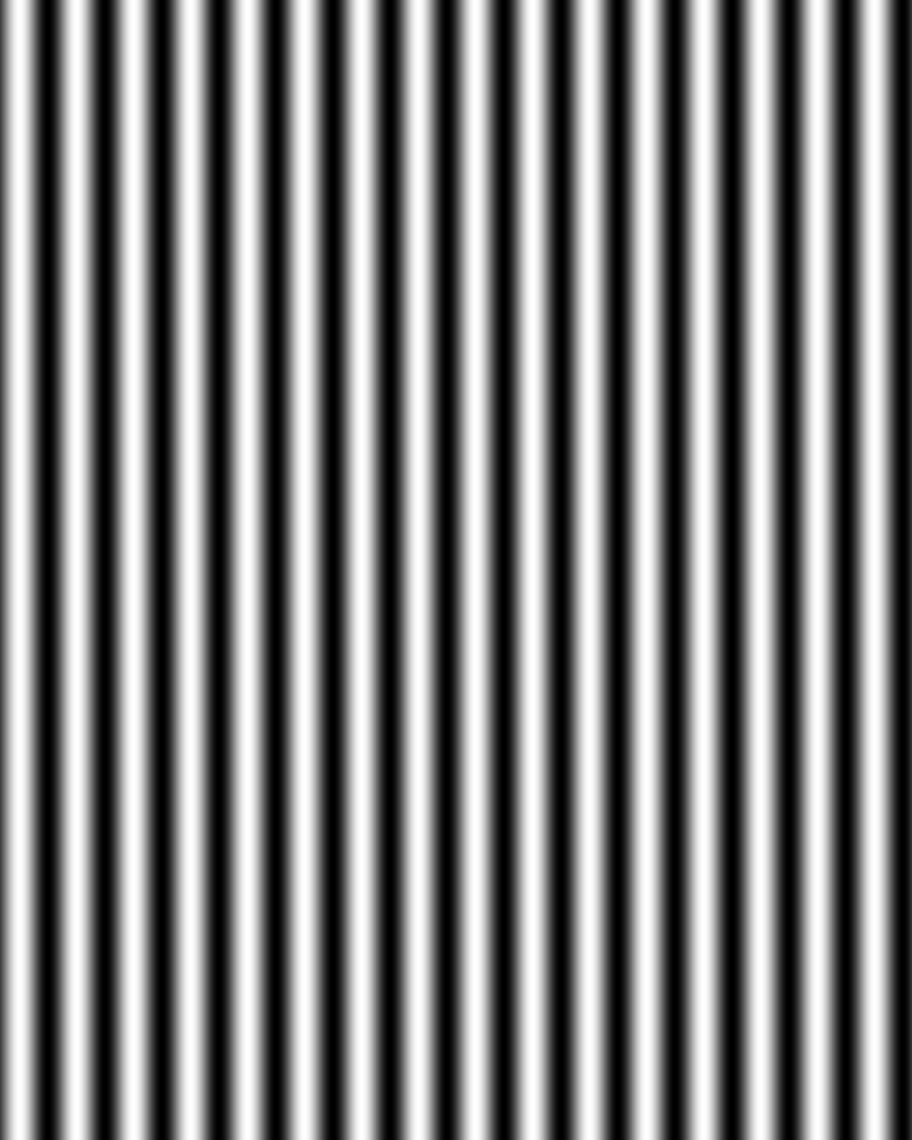
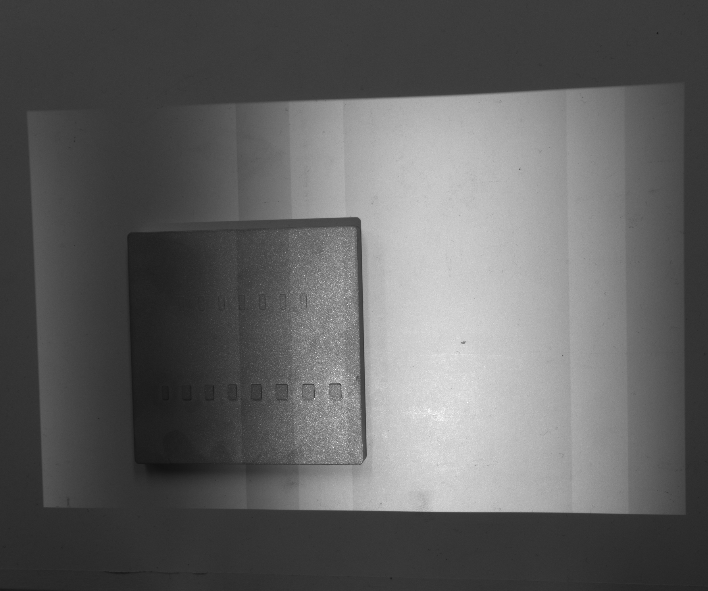
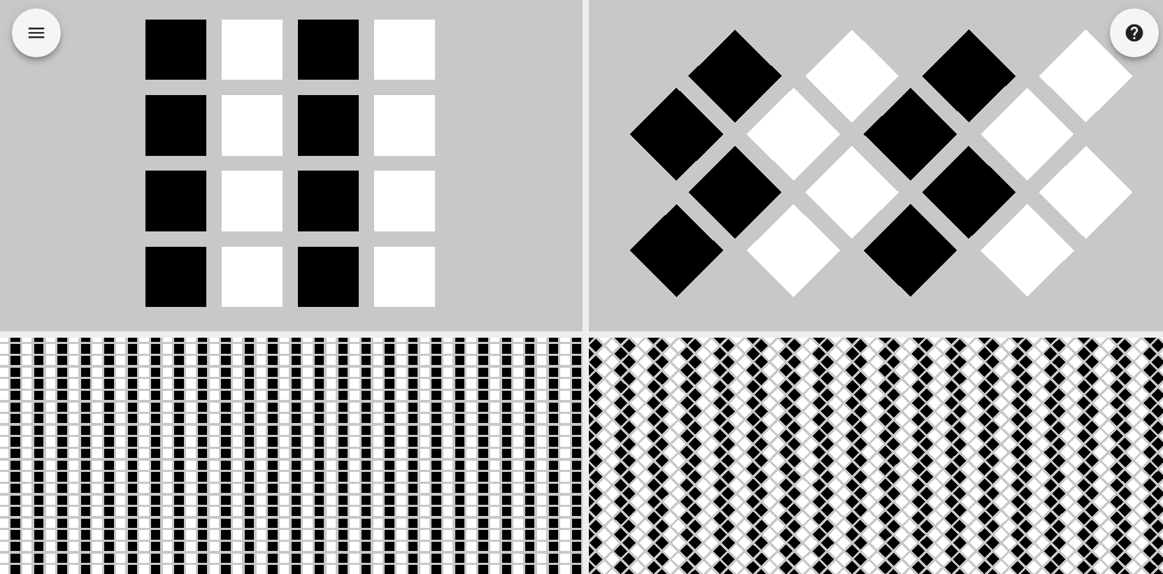
As a test I would like to displaysix images on the 4500EVM and capture them manually through my camera. See images below

I have looked at the training videos and I just want to clarify that I am doing this correct or if there may be an easier alternative.

Each image is 8 bit

As best I can tell I should

  1. Create a 24 bit image with the first three images.
  2. Create a 24 bit image with the second three images. 
  3. Create a version of the firmware with these two new 24 bit images
  4. Upload the firmware

Questions

  1. The DLP Lightcrafter GUI is different than the training videos. How do I create my own .bin file with my new patterns
  2. When they are uploaded to the lightcrafter what is the simplest way to display each of the 6 images manually? Basically I just want to take a picture on the object with each of the patterns
  3. Is the approach I am taking correct? Is there an easier way? (not normal video mode as the video card is altering these images before sending them to the lightcrafter - gamma etc..)
  4. Can I use windows 10 to upload the new firmware?

Thanks

  • Hello John,

    Yes, your four steps sound correct. As for your questions:

    1. Could you confirm what training videos and what GUI version you are using? I believe the training videos may have been made before the latest GUI update.
    2. Do you want to sync the images with an external trigger? Or do you want them to run automatically at a given framerate.
    3. So far sounds like this is the correct approach. Let me know about how you are trying to sync the images with the camera though.
    4. You can try to use the GUI on Windows 10. Some of our customers have been having difficulties though related to the GUI on Windows 10. Last time I used the GUI it did work on Winodws 10. So your results may vary.


    Thanks,
    Kyle
  • Hi Kyle,

    Thanks for the feedback so far.

    This is an experiment we are trying to perform based upon fringe projection and extracting 3D point cloud from the images.

    To keep it relatively simple we were going to trigger the camera capture manually so we were hoping to show each of the images for a period of time ( say 3s each frame)  and snap a camera image during the 3s interval. We can automate the process at a later stage

    The GUI version is 3.1. I found an updated training video that resembles more the GUI that is in 3.1 but I am still a little unclear of the following.  

    How do I show the fringe pattern once it’s uploaded as part of the 24 bit image?  I couldn’t see from the video how you would show an image like I have attached. It showed more how to show red green and blue patterns.

    Hope this helps clarify but let me know if you need more detail

    Thanks

    John

  • Hi Kyle,

    I forgot to add the link the training video I was looking at. Like I said I think the difficulty we are having is how to 'play' our image pattern once we upload it. We will have 12 in total we need to sequence through

    Thanks in advance

    John

    https://www.youtube.com/watch?v=Igw9I877kAM

  • Hi Kyle,

    Sorry for nagging you. Any luck in figuring out my question on how to display the fringe patterns on the 4500? I'm under pressure here in work to get this resolved.

    Thanks in advance

    John

  • Hi Kyle,

    I managed to upload and pull out the images from the firmware over the weekend. One last area I am struggling on.

    Based upon the image above which is 912 x 1140 how do I modify this to take into account the unique diamond configuration of the 4500? 

    If I don't alter it and leave it as it currently stands what artifacts will I see for my given image after it is projected through the 4500?

    Thanks in advance

    John

  • Hello John,

    Sorry for the delay. I am glad you have been able to get this working. If you are using pattern mode you can feed in a 912x1140 image and it will map directly to the DMD. It will obviously different being projected than on your monitor thought as its being displayed using the diamond pixel layout. See the following E2E posts for explanations and let us know if you have further questions:
    e2e.ti.com/.../571151
    e2e.ti.com/.../1649681
    e2e.ti.com/.../2464295

    Thanks,
    Kyle
  • Hi Kyle,

    Still a little confused on this one. In some of the posts you highlighted above it says I would need to alter the image and in another it says I can directly upload the 912 x 1140 pattern and it will just work.

    Saying that I have uploaded the pattern as 912 x 1140 and it looks OK when I display it bar the the image seems to be banding.

    See this image

    Is this related to the post I have linked below? I get the same problems when I display the internal pattern ramp. Any ideas?

    https://e2e.ti.com/support/dlp/f/94/p/168279/618397

    Thanks

    John

  • Hello John,

    You can display a 912 x 1140 image and it will be displayed pixel perfect. The confusion comes related to the fact that it will be pixel perfect in regards to a diamond grid. Therefore, it will appear to be stretched in the x axis . The only reason you would need to modify the image is if you designed your patterns without taking into account the diamond pixel mapping. See an example below of how vertical lines in an orthogonal array would map to a diamond array. 

    Thanks,

    Kyle 

  • Hi Kyle,

    I understand now. Just on that last question I had. Any ideas on the banding? I can't seem to get a linear horizontal ramp using the internal pattern or a pattern sequence that I create myself.

    Thanks in advance

    John
  • Sorry Kyle - I had done something stupid with regards to the banding problem. All good now. I'll mark this as resolved.

    Thanks for your patience

    John