This thread has been locked.

If you have a related question, please click the "Ask a related question" button in the top right corner. The newly created question will be automatically linked to this question.

DLP6500FYE: DMD display is not normal , grayscale contrast is very poor

Part Number: DLP6500FYE
Other Parts Discussed in Thread: DLPC900

Hi

Refer to the 6500EVM design. I tried to design a 6500FYE system.

Now I have a fatal problem,in my design, the gray scale of the DMD display is very weak.   the DMD chip is good because it works fine on the 6500EVM(same DMD chip).

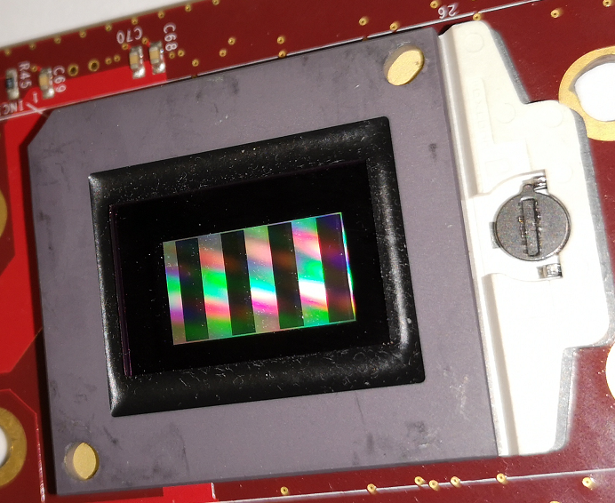
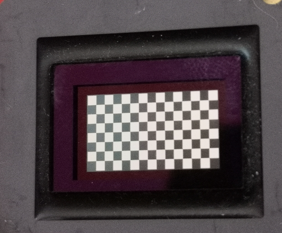
On 6500EVM is works fine, every picture can be seen very clearly,You can easily find a clear viewing angle:


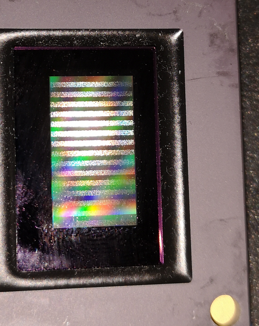
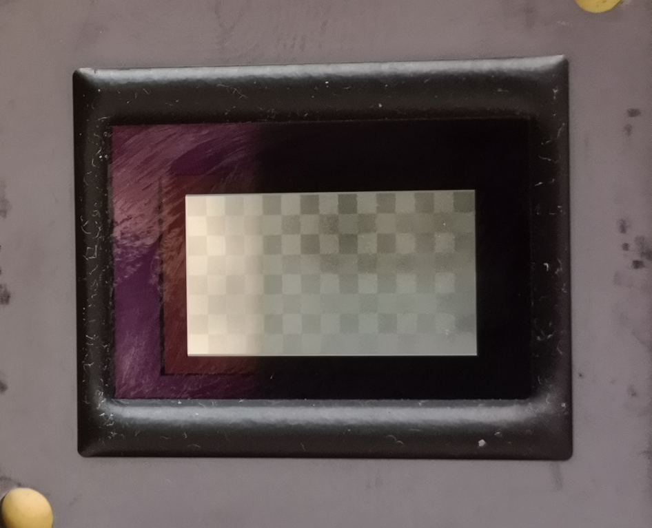
On my design ,you can hardly find a clear viewing angle,and the grayscale contrast is very poor:

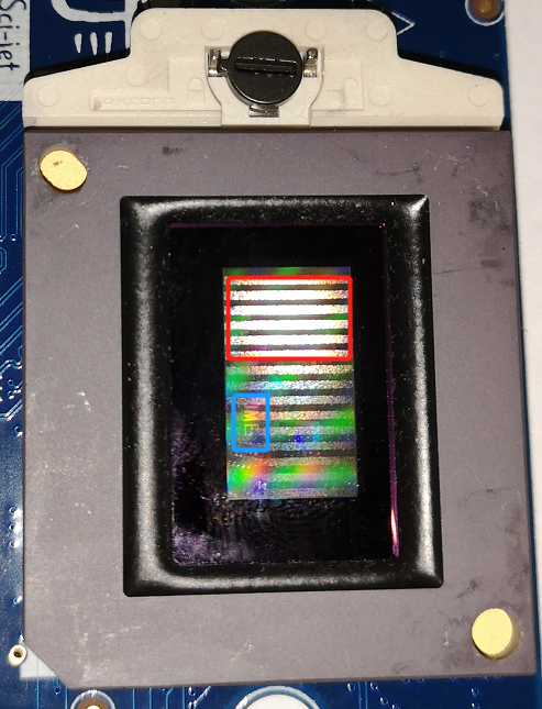
most of the viewing angles are like this,as in the red box, there are some static bars. The blue box is faintly visible display text

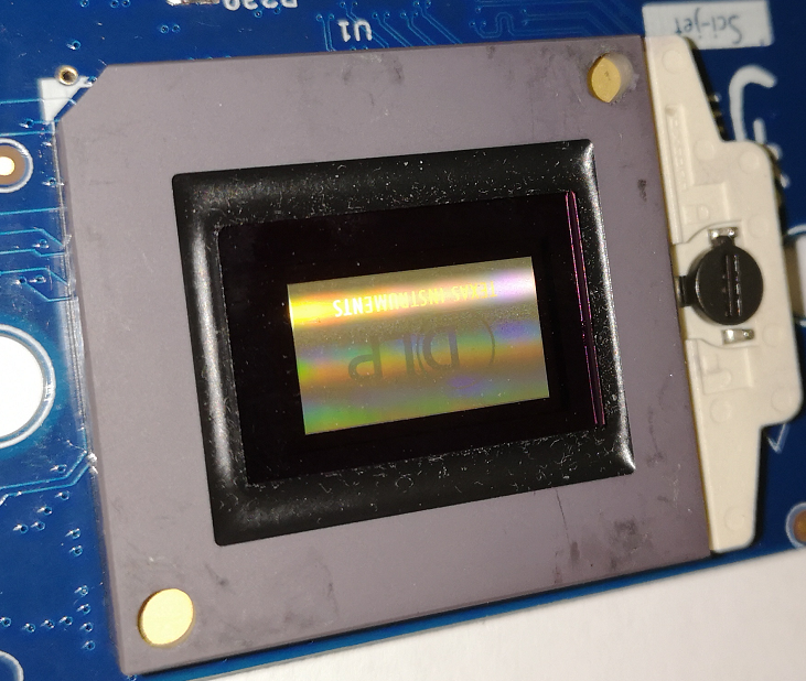
Display after turning off the power:

I measured several voltage signals of the DMD:

VCC & VCCI:  3.23 V

VOFFSET:  8.41 V

VRESET:  -9.99 V

VBIAS:  16.24 V

The voltage signal looks like normal,  i don't know how to start troubleshooting,  I really need your help.

Best regards,

Byron

  • Hi Byron,

    Please check connections between DMD and DLP900 are correct and signal integrity rules are followed in board layout.

    -ykc
  • Hi ykc

    thank you for your support.

    I think the probability of signal integrity is low. More like a signal is disturbed or "insufficient power".

    Signal integrity issues have appeared in the first edition, and the phenomenon at the time was that the Pattern display was incomplete.The current phenomenon is that the Pattern display is complete but the display is very dim.

    So can you provide some test methods to locate where the problem is? Such as Test point or special operation methods.

    Byron
  • Hi Byron,

    The pictures attached by you contains stripes? Is display correct as per image loaded and only problem is brightness?
    If brightness is only problem please try increasing led pwm duty cycle.

    -ykc
  • Hi ykc

    This is the boot display of the default firmware.

    The display is weaker and has no relationship with LED illumination (already excluded). The problem is above the display of the DMD . DMD's display is very dim.

    At a specific viewing angle as shown in the third picture. You can see the complete pic or see it through the optical system and these stripes can be seen at other angles(not my load), and the stripes are fixed even after power is off.

    Byron
  • Byron,

    Ok I understand. DMD is just mirrors on/off. It has no light source of its own. Since you not seeing same as EVM there is something wrong in HW.
    Are you able to connect your HW to EVM GUI? If yes set it to checkerboard pattern instead of rotating patterns and provide me picture at same angle for both EVM and your HW.

    Also please share your schematics and layout.

    -ykc
  • Ykc

    I have tried this before but got the same phenomenon. I am worried that if you shoot at the same angle (WVM and HW), HW may not be able to capture the picture displayed.

    I will try to reproduce it, it will take a little time.

    I apply for a friend and send you a message.
  • Byron,

    I looked at schematics. I suspect Flex cable connector in your system is not same as EVM. Note that EVM flex cable does not map pin to pin from controller side connector to dmd board side connector.

    E.g in your schematics DCLKB_P on controller is connected to M_DCLKA_P i.e E4 of connector on controller board. E4 pin on DMD connector side is also M_DCLKA_P and it is connected to DCLK_AP. If your flex cable map pin to pin on both connector side then it will connect DCLK_BP to DLCK_AP.

    Please verify the continuity from controller pins to dmd pins.

    -ykc
  • ykc

    EVM :

    HW:

    HW is more difficult to take a clear picture.

    I found that the DADSTRB signals on the two boards are different?  How does this signal work?

    thank you very much for your help!!

    Byron

  • Byron,

    Reset Address, Mode, & Level latched on rising-edge of strobe signal. This signal will go high before MBRST is done.

    -ykc
  • ykc

    Thank you for your patience.

    If M_DCLKA and M_DCLKB are connected incorrectly, will the DADSTRB signal behave abnormally(Compare to EVM)?

    I am worried if there are other reasons that will cause the DADSTRB to be different.

    Byron
  • Byron

    DADSTRB is used to start latch DMD reset information. It is not related to DCLKA and DCLKB. DCLKA/B are clocks for LVDS bus that is used to load data. Data takes effect on mirrors when DADSTRB is asserted and command is sent.
    Below is connection from Controller to DMD without flex cable.

    DLPC900 DLP6500FYE
    DDA_P[15:0] D_BP[0:15]
    DDA_N[15:0] D_BN[0:15]
    DCKA_P DCLK_BP
    DCKA_N DCLK_BN
    SCA_P SCTRL_BP
    SCA_N SCTRL_BN


    DDB_P[15:0] D_AP[0:15]
    DDB_N[15:0] D_AN[0:15]
    DCKB_P DCLK_AP
    DCKB_N DCLK_AN
    SCB_P SCTRL_AP
    SCB_N SCTRL_AN

    DADADDR_0 A0
    DADADDR_1 A1
    DADADDR_2 A2
    DADADDR_3 A3

    DADMODE_0 Mode0
    DADMODE_1 Mode1

    DADSEL_0 Sel0
    DADSEL_1 Sel1

    DADSTRB Strobe
    DADOEZ OEZ
    DAD_INITZ IRQZ
    EXT_RSTZ RESETZ

    SSP0_CLK SCPCLK
    SSP0_TXD SCPDI
    SSP0_RXD SCPDO
    SSP0_CSZ1 SCPENZ


    -ykc

  • ykc

    Thank you for your reply, I am just worried about the misplaced line order in the schematic.

    byron