This thread has been locked.

If you have a related question, please click the "Ask a related question" button in the top right corner. The newly created question will be automatically linked to this question.

DLPNIRNANOEVM: 4 light module modification problems

Part Number: DLPNIRNANOEVM
Other Parts Discussed in Thread: DLPC150, OPA567, INA213

Hi,

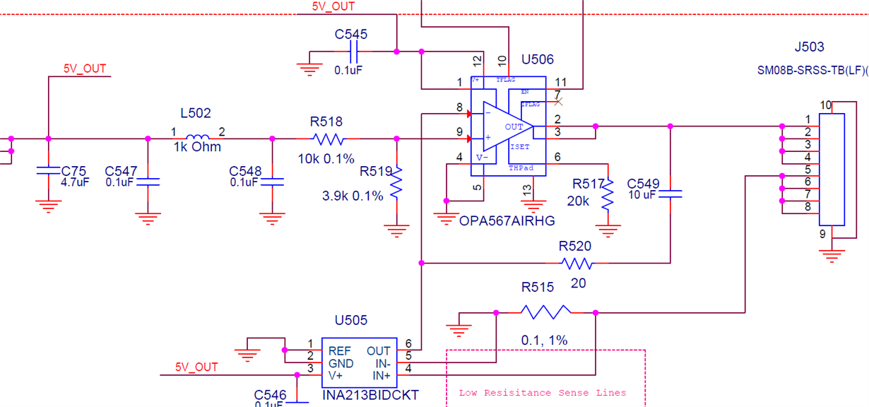
In order to get some more lightning power we build a 4 lamp module with the body thats available from TI. We use 4 lamps that draw 125mA each. In the manual that  TI provides, an example was made wich resistors has to change when asking more current of the onboard lampdriver.

In attached picture we changed  R519 with a 10K resistor and R517 with a 12K. When starting our test, the lamps did not lit up. I measured a voltage of 5V without the lamps attached. But as soon the lamps are connected the voltage climbs not above 0.18V. It seems that the current is highly limited. Did I made a mistake with resistor values maybe?

Kind regards

Ben Teugels


  • Hello Ben,

    Welcome to e2e forum and Thanks for showing your interest in DLP Technology.

    Give us a some time to understand the behaviour and we will get back to you with required information soon.

    Thanks,
    Navneet
  • Hi Ben,

    As per my calculation, R519 should be >15k to support >500mA current through the opamp. Also, kindly check the source code. There is a file named dlpc150.c. In this file add this line at the top : 

    #define FOUR_LAMPS 1

    And then rebuild the NIRScan Nano binary and upload. This binary should allow a higher current limit. 

    Hope this works,

    Thanks & Regards,

    Hirak.

  • Hi Hirak,

    Thank you for the reply. Would you mind to share your calculations? I'm curious what went wrong with mine.
    Is the limitation in current a combination of the resitstance values on the main pcb and a limiter in the software? Or does this source code change also controls extra features to supply the power to the lamps? I saw that there are expansion possibilities with the connector thats used to connect the lamps to the main board. As we where not able to identify the used connector we just used the wiring of the 2 light module and connected 2 extra lamps in parallel with the existing lamps.

    Can I ask you another question? The model of the 4 light module as downloaded from TI does support the light sensor thats used in the 2 light module. Does the software use a standard value for the transmitted wavelenght of the light source when the sensor is disconnected, or is the value from a disconnected sensor then used instead? I guess there are some other required modifications in the source code that has to be made?

    Thanks in advance

    Kind regards

    Ben
  • Hi Ben,

    Kindly wait for a few more days, this is getting delayed because of the vacations.

    Thanks & regards,
    Hirak.
  • Hi Ben,

    Kindly find my calculations below:

    The input to the OPA567 pin9 is, V9 = 5V*{R519/(10k+1k+R519)}

    now if the current flowing through the lamps be 500mA, then the input to the INA213 will be 0.5*0.1=0.05V

    Therefore the input to the OPA567 pin8, V8 = 0.05*50=2.5V

    now, equating V8 & V9, we get R519 to be 11k. 
    To account for the inaccuracy of the IC and the resistors, a safe value seems to be around 12-15K. 

    And regarding to the other query, you don't need to change the source code to support greater current. That was a mistake. The current is not anyway controlled by the software. Since you are using 4 lamps instead of 2, a new reference scan will be required. Since the lamp characteristics may change with time, it is good to have periodic reference scans.

    Hope this answers your queries, 

    Thanks & Regards,
    Hirak.