This thread has been locked.

If you have a related question, please click the "Ask a related question" button in the top right corner. The newly created question will be automatically linked to this question.

DLP3010EVM-LC: Get video information error

Part Number: DLP3010EVM-LC
Other Parts Discussed in Thread: DLPC3430

I recently purchase a DLP3010EVM-LC. Initially, I was able to successfully set it up and operate it through the DLP GUI (v2.1.0.7). I was also able to successfully deploy the updated firmware (v 7.3.1) as well, and continue to operate it afterwards. Specifically, it was still able to display a clone of my computer screen or display custom patterns through the GUI.

In a subsequent session with using the device, the DLP GUI started giving me an error message "Get Video Information Error! Error while trying to gain access to the I2C bus" when I hit any "get" button. As far as I can tell, I have reassembled the entire system exactly as described in the DLP3010EVM-LC user manual. In the EVM information, it is able to recognize the DLPC3430 controller, but is unable to recognize the DMD or the PMIC/LED driver. Upon power up, D5 and D6 LEDs are appropriately lit. D1 and D2 are also lit. When switching the projector to the on position, D3 lights up. However, the RGB LEDs no longer are powered and there is no image projected from the system. If an HDMI cable is attached, the MSP2/D7 LED lights up as well. The fans continue to operate normally. It is still possible to successfully redeploy the firmware update to the system, although doing so does not appear to make any meaningful change in the system operation.

Please advise. Thank you.

  • Hello UCIBCITeam,

    You mentioned you "reassembled the entire system", does that mean you made some modifications? If so what were they? Also are you able to succesfully perform any other commands from the GUI?


    Thanks,
    Kyle

  • We didn't make any modifications to the board, but we examined the interface board, the DLP controller board, and the DMD ribbon connector to better understand the system design, and them snapped all the parts back together. Proper grounding protection was used to avoid damaging the boards with static discharges.

    We are confident that they have been reassembled correctly, but can provide images if necessary.

    At this time, any command from the GUI results in a similar I2C error.

  • Hello UCIBCITeam,

    I am not sure, what could go wrong in this scenario.

    As you mentioned, you are seeing "D1 and D2 are also lit" are these LED's are not turning off after sometime ?

    D1 Led should be on during bootup and then turnoff after bootup completes, after it goes off projector is ready to receive the commands. If this LED is not turning off that means there is a issue in bootup. 

    If this is the case and you are seeing the issue in bootup, there is two way to go forward :

    1. upload the firmware again, in case firmware got corrupted.

    2. If firmware is okay, then you need to debug the hardware - starting with DLPC voltages, you can see the DLPC voltages in DLPC datasheet and you can refer the EVM schematic to see the probing points. Another you can see DLPA voltages are properly driven from DLPA (see the DLPA datasheet for voltages).

    If all voltages are good then we need to check your reassembling.

    Please make sure all the connection are tight, i meant LED and DMD flex connections.

    All the best for Debug, let me know if you need anything from me.

    Thanks,

    Navneet

  • Thanks for the follow up.

    I was able to re-upload the firmware successfully. The D10 LED constantly flashes during this process, and GUI confirms that the process was successful. However, it does not appear to change anything. The GUI still says the EVM status is: "connected, powered off"

    The D1 and D2 LEDs remain lit and does not ever change. The only time it changes is when I flip the projector switch to the on position. In this case, D1 stays lit, D2 turns off, and D3 turns on.

    I have made sure that all the connectors are tight, including the interface/controller board connector (J5, J9), as well as the DMD flex connector. I also used compressed air to make sure that any dust interfering was blown off. Likewise the LED connector is also tightly plugged in. All the screws were secured tightly to ensure a good connector and stable board positioning.

    Regarding voltages, both D5 and D6 are lit to indicate that the 5V and 3.3V lines are online. I checked the pins of J11 and found that the 1.8 V and 3.3 V lines are intact as well.

    For J2, the blue line reads: 1.5V, green line: 1.5 V, red line: 2.5 V, and white line: 3.5 V. I am not sure what the significance is, but I suspect it means that the LEDs should be getting power supply, although it does not appear that they light up when the projector switch is on. When the projector swith is off, all of these lines are 0V. Based on the schematic, it appears that the 3.3 V supply (tested at R18 and R17) are both reading 3.3 V. The 5V rail, tested at J2 appears to be correctly reading 5V as well.

    Are there any other test points in particular that I should check?

    Also, one other note is that when the projector switch is turned on and I attempt to press any "get" button on the GUI, it reads: "Get Video Information Error! 'Read Operating Select Mode' command execution failed. Error details: Failed to read I2C port via Cypress USB-serial adapter."

  • Hello  UCIBCITeam,,

    Looks like EVM is failing in the bootup, D1 LED should be turn off after boot up complete and then DLPC is ready to receive the command. That's why you are seeing error in GET command.

    I can not say what could go wrong, but can you please check all voltage supplies going to DMD.

    Also, please check you have installed all the jumpers correctly, as mentioned in user guide. 

    Please send the images of your setup.

    Thanks,

    Navneet

  • The only jumper mentioned that should be installed onto the board is for J11, which is used to select the trigger in/out voltage. I installed to select the 3.3V mode. This did not make any difference in the behavior.

    In checking the voltages on the DMD/DLP controller daughter board (projector switch in on mode), the V2V5 test point reads 2.5 V, the V6V test point reads 6.25 V, LS_PWR and LS2_PWR read 0 V, VRST is -14V, V0FS is 10V, VBIAS is 18V, CSZ is 3.3 V, while other SPI related lines read 0V (MISO, MOSI, CLK).

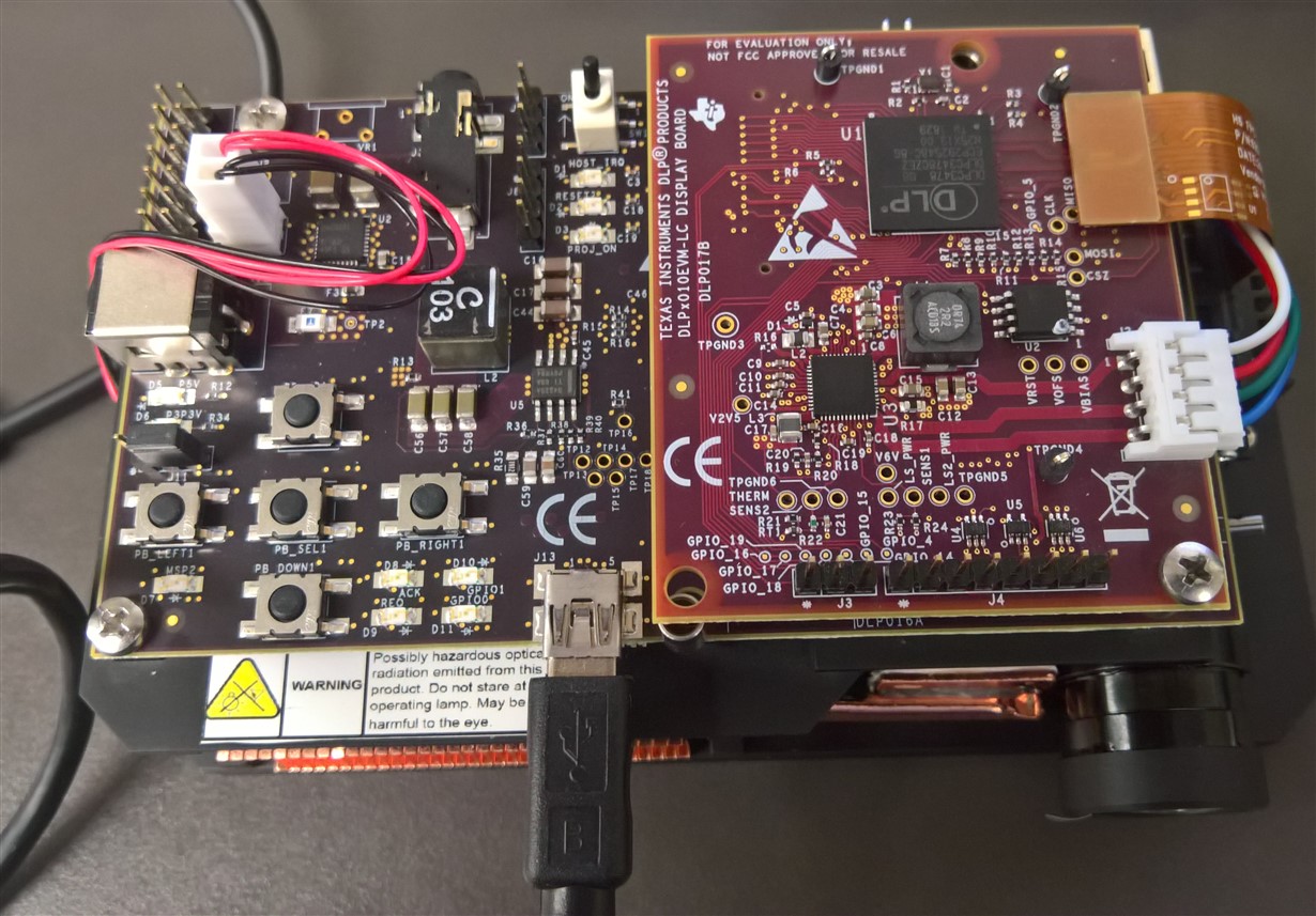
    A picture of the setup is shown below. Note that the top retaining bracket is removed for clarity of the DLP controller daughter board. Please let me know if any other photos are needed. Thanks.

  • Hello Team,

    First we need to get the HOST_IRQ low, (HOST_IRQ low means bootup process complete).

    Can you please probe the following voltages coming out of DLPA (1.1V, 1.8V, 3.3V) - see the schematic for reference. Also check these signals continuity with respect to ground. (removing the doubt of shorting to ground)

     please share the status of these signals too - PROJ_ON, RESETZ, and INTZ, LED_SEL_0, LED_SEL_1.

    Thanks,

    Navneet