This thread has been locked.

If you have a related question, please click the "Ask a related question" button in the top right corner. The newly created question will be automatically linked to this question.

DLPDLCR2010EVM: DLPDLCR2010EVM-PCB

Part Number: DLPDLCR2010EVM

Hi, 

I have DLPDLCR2010EVM-PCB. Before powering it up, I detached the upper board "DLP board" and connected a 5V, 3A adapter to the board. Only one LED was on "SYSPWR". However, I noticed that U12, U9 and U1 were getting very hot. Hence I disconnected the power and found that U9 looks burnt (I am not sure). measuring the resistance between the positive and negative pins of the input, I found it 6 Ohms. This means that there is a short circuit somewhere. To measure the powers, I had to connect the power again and remove it within few seconds to avoid the heat. The measured voltages were: 
U1 = 1V6

U12 = 1V8

U17 = 0V8

As you can notice, these numbers are not as expected from the schematics. Do you have any suggestion? 

It was the very first time to operate the EVM!

Kind regards,

Anas

  • Hello Anas, 

    This typically happens if an input voltage is getting applied to the EVM which is above 5V or a short of the 5V has occurred on the board. 

    The only way to recover from that is to start replacing parts which are connected to the 5V rail and remove the short to GND this way. 

    Best regards,

    Nadine 

  • Hi Nadine,

    Many thanks for your reply and your guidance.

    Due to some time limitations, I had to operate another brand new EVM I had. Using "PW172KB0503f01" as a power adapter, the main board seemed to work properly alone. Once the DLP board was attached, DLPA2005 blew up and there was some smoke. Any idea why this happened? 

    Kind regards,

    Anas

  • Hi Anas, 

    Did you have an optical engine with LEDs connected when operating the board?

    Thanks, 

    Brandon

  • Hi Brandon,

    No. It was just the DLPDLCR2010EVM-PCB.


    Regards,

    Anas

  • Hi Anas, 

    That would do it! The DLPA2005 board requires an LED load to operate properly. The EVM should not be oeprated without an optical engine with LEDs attached. 

    Thanks, 

    Brandon

  • Hi Brandon,

    Thanks a lot for the reply. 

    In fact, I will not use the board as a projector. Instead, I will use it to build an optical system which does not require any LEDs. Do you have any advice for that?

    Otherwise, I will have to connect the LED loads without using them.

    Many thanks in advance.

    Kind regards,

    Anas

  • Hi Brandon,

    Another question, am I expected to connect a light sensor to J4? 

    Kind regards,

    Anas

  • Hi Anas, 

    For correct operation of the DLPA2005, LEDs are required. One way you may be able to not have LEDs connected would be to connect diodes with similar characteristics instead of the LEDs. We have not tested this, as we always have LEDs connected. 

    As for J4, a light sensor is only required if you would like to use the white point correction feature.

    Thanks, 

    Brandon

  • Hi Brandon, 

    I was checking the schematics of the DLPNIRNANOEVM and I noticed that for DLPA2005, pins 37, 38, 39, 41 and 42 are not connected to any LEDs. These are typically the pins that power the LEDs up in the DLPDLCR2010EVM-PCB. Hence, I am afraid that connecting these pins to LEDs will not solve the problem. I did not try to power the board on as I am afraid that the new DLPA2005 would blow up again!

    Thanks for your help.

    Kind regards,

    Anas 

  • Hi Brandon, 

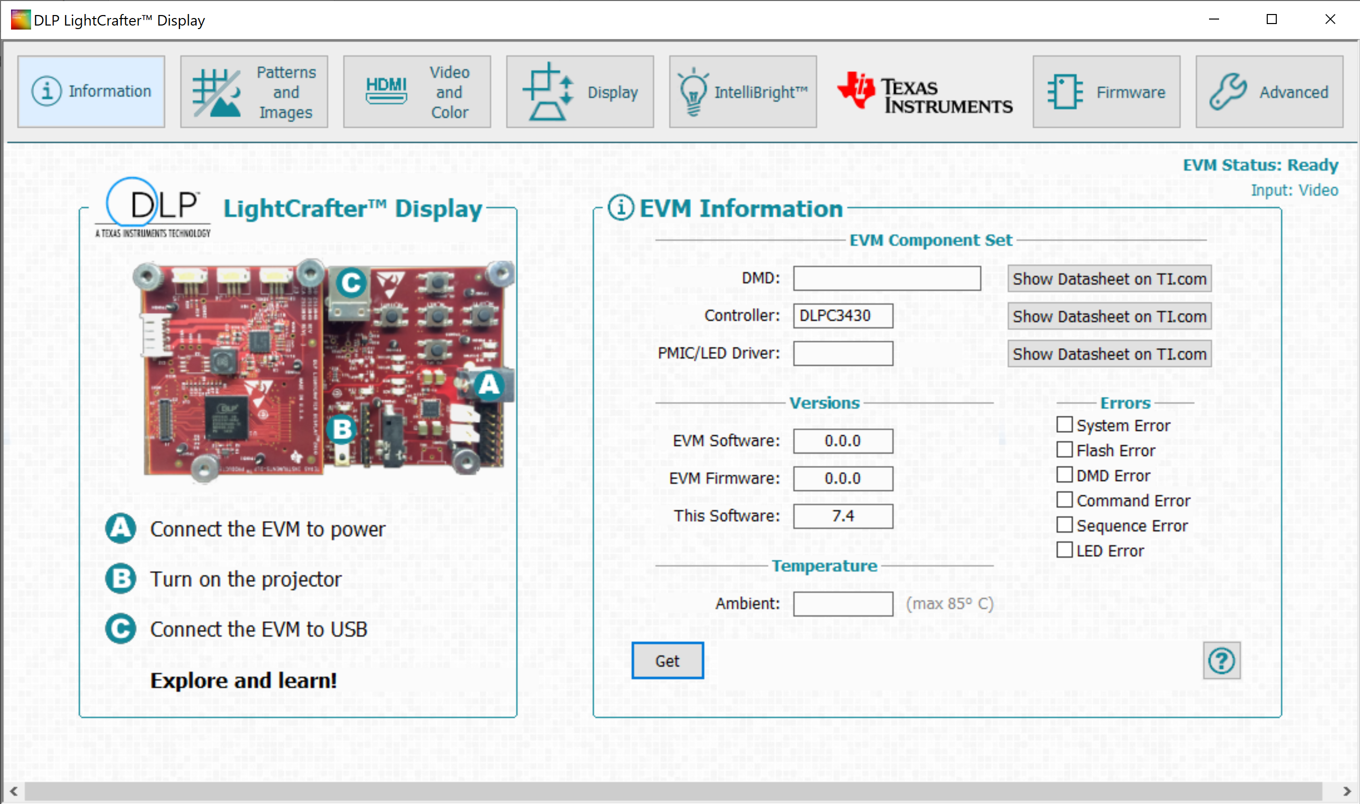
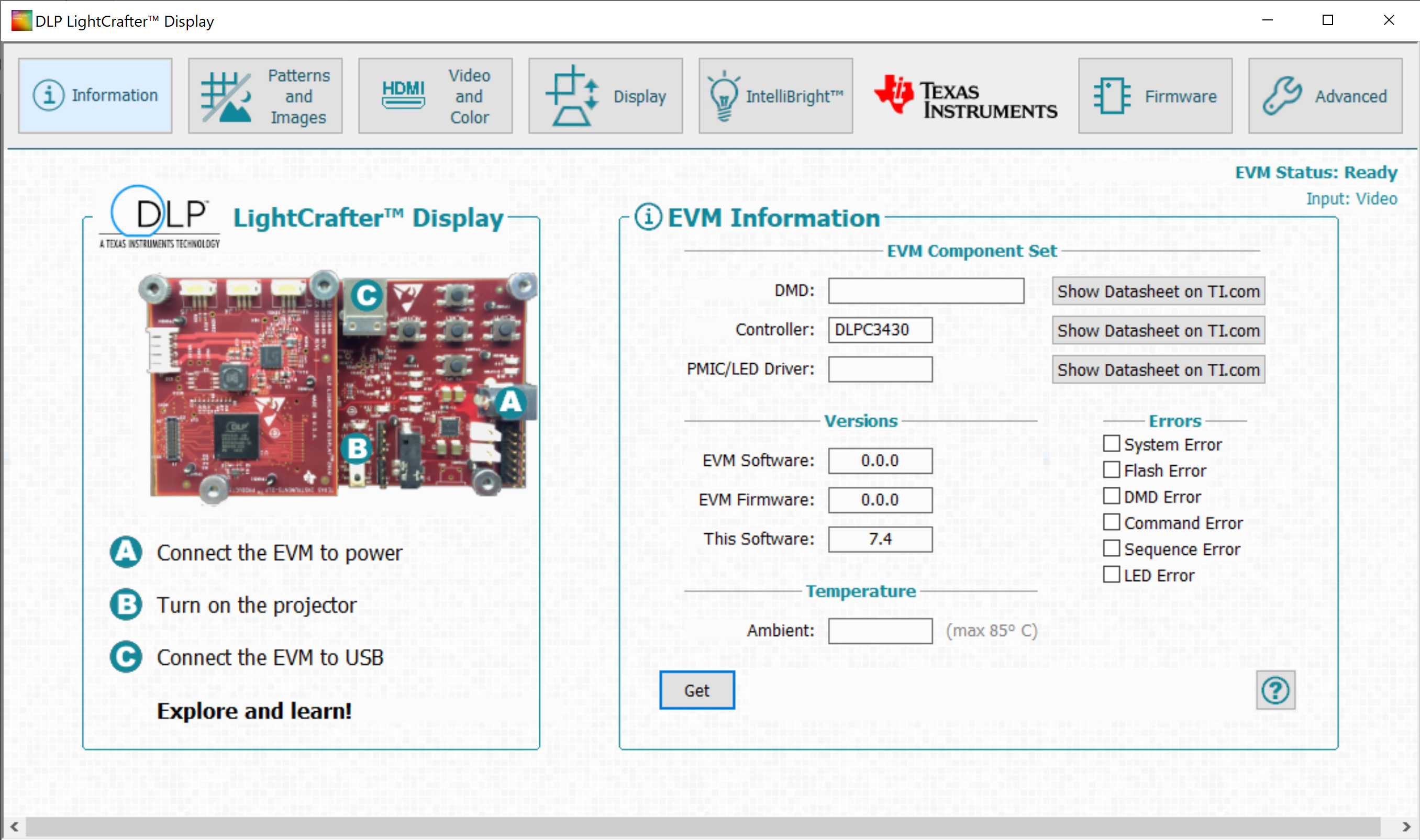
    I replaced the DLP board with a brand new one then connected the LEDs as recommended to J2. The board works now and LEDs D15, D16, D5 and D7 turn on when the board is live and the projector is on. However, after connecting the board to my PC, the provided GUI tool recognized DLPC3430 as shown in the attached file but did not recognize either the DLPA2005, EVM software or the EVM firmware. Will it be possible to fix that?

    Thanks in advance.

    Kind regards,

    Anas

  • Hi Anas, 

    Do you have a DMD connected in addition to the LEDs?

    Thanks, 

    Brandon

  • Hi Brandon,

    No actually. I didn't connect it. I will connect it and try again.

    Thanks for your help.

    Kind regards,

    Anas

  • Hi Anas,

    No problem! The DLPC3430 shuts down when a DMD is not detected, so that is likely why you were not able to communicate with the DLPC3430 over the GUI.

    Thanks, 

    Brandon

  • Hi Brandon,

    But is it normal that the EVM software and EVM firmware are 0.0.0?

    Kind regards,

    Anas

  • Hi Brandon, 

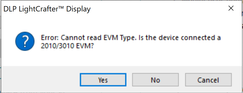
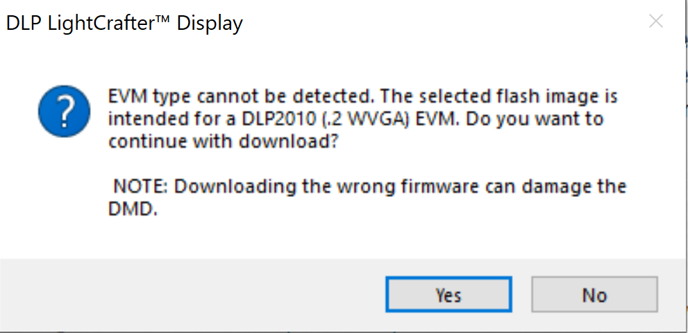
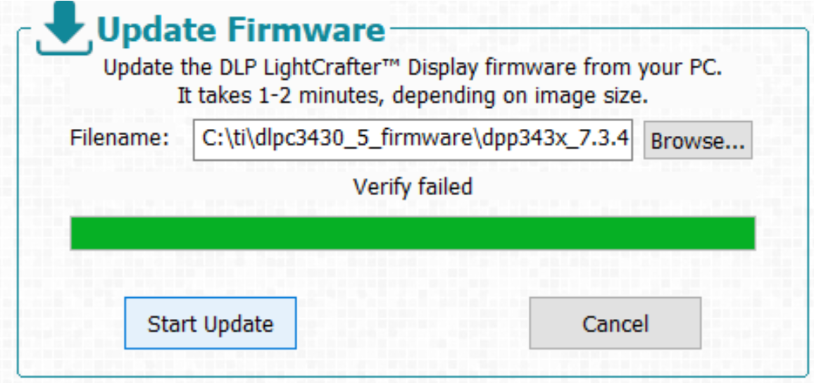
    As the software did not recognize the EVM software nor the firmware, I tried to install the firmware on the external Flash memory I installed. Hence, I tried to do that through the software and I got these messages. 

    Unfortunately, this did not work. Do you have any idea how to solve this issue? 

    Kind regards,

    Anas

  • Hi Anas, 

    Were you able to connect a DMD in the system? Please try this an see if the EVM creates an image. 

    If you connect the DMD and no image is created by the system, you may have corrupted the image. To fix this, power the EVM on but do not flip the proj_on switch and try to re-download the image. 

    Thanks,

    Brandon

  • Hi Brandon, 

    Unfortunately, this did not work. To summarize, the problem now is that the software does not recognize neither the EVM firmware nor the EVM software, is this normal for DLPDLCR2010EVM-PCB? 

    In addition, I am not able to install the firmware through the software. Finally, there is no image shown on the DMD even after re-downloading the image. I am not sure if the image is re-downloaded successfully as it is not shown in the software.

    Thanks in advance. 

    Kind regards,

    Anas

  • Hi Anas, 

    Thank you for your quick reply. Let me summarize this situation to make sure I understand everything correctly, as you have tried many different things to get your EVM working. I have not seen the firmware version read back v0.0.0 before and I do not believe this is normal. 

    1. You purchased a DLPDLCR2010EVM-PCB EVM from TI store or a distributor. 

    2. You tried to power on the EVM (without LEDs or a DMD connected) and that caused damage to the EVM. 

    3. You replaced the DLP board with a new board, and tried to communicate with the EVM. The GUI was able to read a DLPC3430 controller in the system, but the DLPA2005 and DLP2010 DMD was not recognized. 

    Where did you get this new DLP board? Did you purchase an additional DLPDLCR2010EVM-PCB, or did you fabricate your own board?

    4. You tried to install the DLPC3430 firmware on the external flash memory. 

    Can you detail the procedure for this? Did you remove the memory from the board? Where did you get the firmware to install?

    Thanks, 

    Brandon

  • Hi Brandon,

    Many thanks for your reply!

    I bought an EVM from Mouser and powered it on without connecting any LED or DMD. Hence DLPA2005 blew up. Therefore I had to replace it by a new one and solder it to the board. In addition, I bought another EVM from Mouser too. Hence, I have two EVMs now. After that, I connected both the LEDs and DMD and powered both boards on. The power consumption was around 105mA with the projector on. Connecting the boards to the PC, I found that the tool did not recognize neither the software nor the firmware of the EVM. This held for the PMIC and the ambient temperature fields in the GUI. I doubted , as there was no flash memory, probably the software and the firmware need to get installed manually on the flash memory. Hence I tried using the GUI Tool. This operation used to fail as shown in the previous attachments.

    Can you help me with this issue?

    Kind regards,

    Anas

  • Hi Anas, 

    Was the entire system only drawing 105mA on both boards (replaced DLPA2005 board and new board), or just the DLPC3430 board? On either of the boards, when connected to the PC, did the EVM GUI tool recognize the software version? 

    It sounds like the GUI tool you are using isn't even recognizing the DLPDLCR2010EVM-PCB straight out of the box. Can you confirm this?

    Thanks, 

    Brandon

  • Hi Brandon,
    The entire system was consuming those 105 mA, the two boards together along with the DMD and LEDs and while the USB is connected.
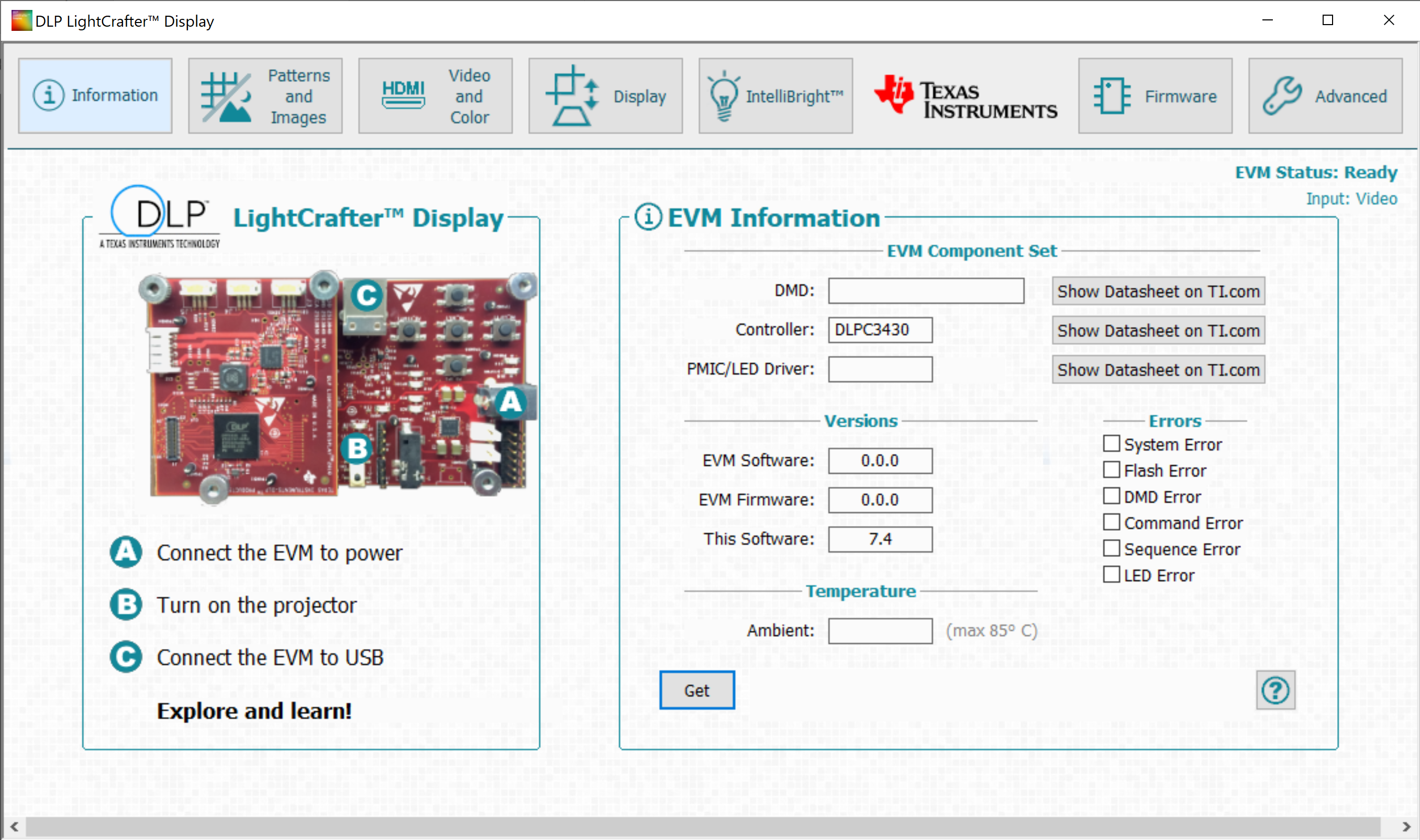
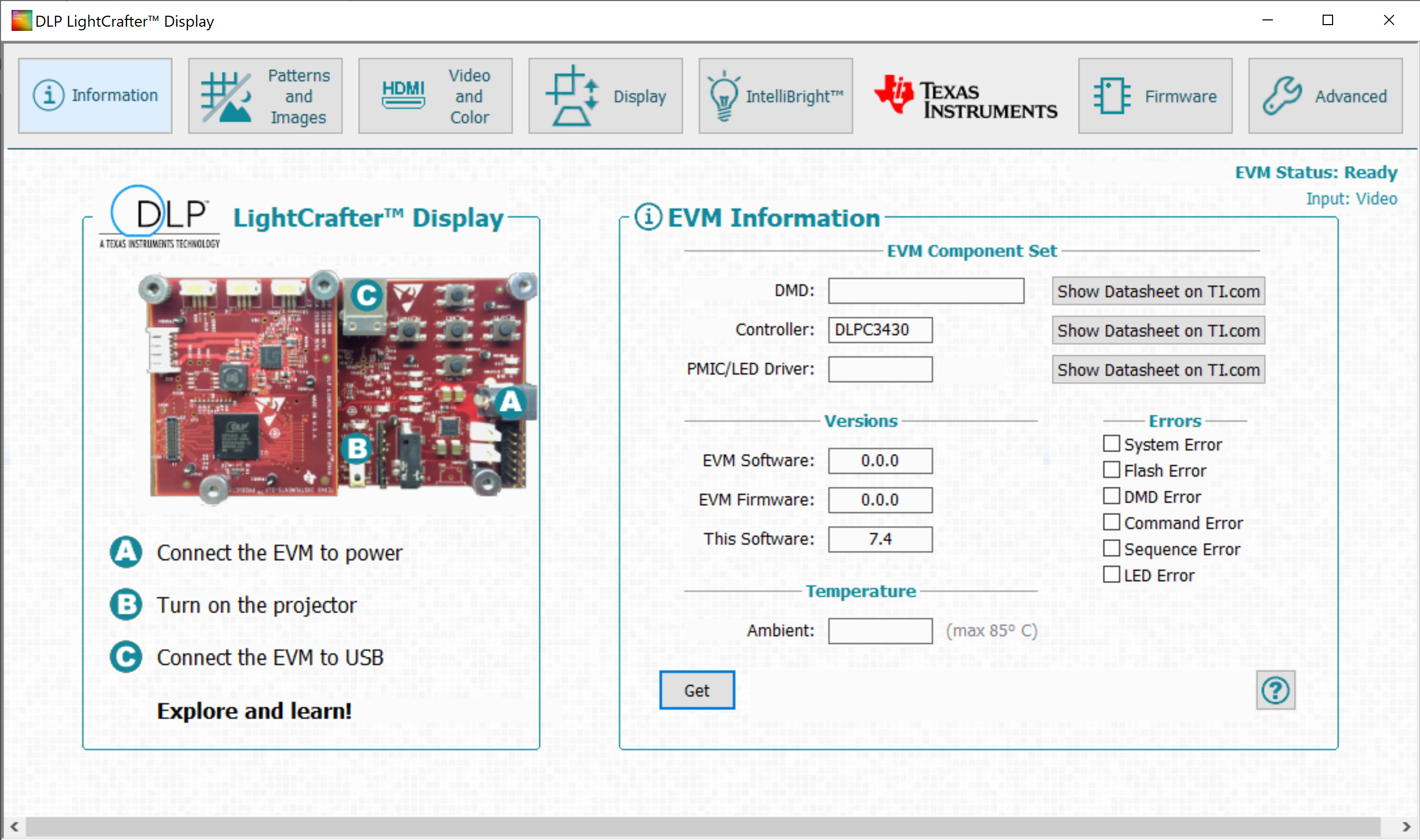
    That's true that the software is not recognizing the EVM. However, it shows that the status is connected and ready. And that the GUI version is 7.4. this is typically what it shows,

    Kind regards, 

    Anas

  • Hi Anas, 

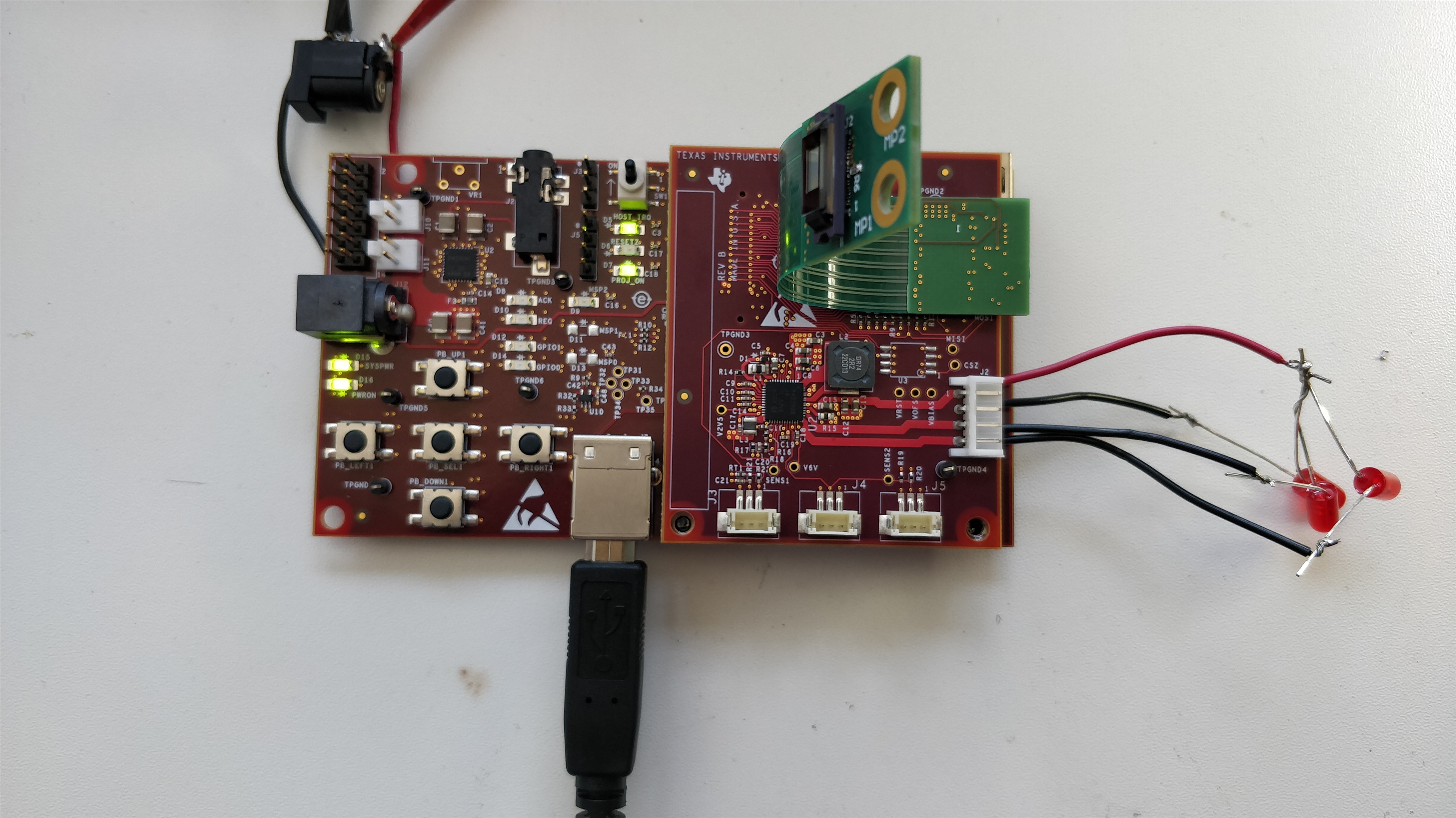
    The entire system should be consuming much for than 105mA. I expect something about 5 times this number when running the system. You said you were able to get an image on the DMD correct? Can you please take a picture of your system and reply to this thread? I believe something may not be connected correctly.

    Thanks, 

    Brandon

  • Hi Brandon,

    Indeed the whole system consumes only 105 mA. Unfortunately there was no image at all displayed on the DMD. I will take a picture and send it in the post, no problem.

    I have a further question, for the EVM you already supply it without a flash memory. Where is the firmware stored then?

    Kind regards,

    Anas

  • Hi Anas, 

    If you are not able to get an image on the wall, then there is something not set up properly in your system. Have you installed a flash memory IC on the light engine? The flash memory IC is on the light engine on this EVM. 

    Thanks,

    Brandon

  • Hi Brandon, 

    Here is the EVM along with all the connections. Yes indeed I installed a flash memory IC in the rigid-flex board. 

    Kind regards,

    Anas

  • Hi Anas, 

    Thank you very much for posting the picture of your system. Which flash memory IC did you install? Are you sure the pin mapping of the flex connector you used in your system is consistent with the DLPDLCR2010EVM? I believe your flash memory isn't communicating with the DLPC3430 controller and the cause may be due to the flex pin map.

    Also, what is the power rating on the LEDs you connected? What is their turn on voltage? I'm afraid the LEDs you chose may damage the DLPA2005. 

    Thanks, 

    Brandon

  • Hi Brandon,

    Many thanks for your reply!

    The pin mapping I of the EVM socket I got it from the schematic files of the EVM published on TI's website. The flash memory I am using is "MX25U8033EBAI-12G". You can find its datasheet in the attachment. 

    MX25U8033E, 1.8V, 8Mb, v1.8.pdf

    For the LEDs, their turn on voltage is 1.8V.

    Another info, the power consumption of the main board only (the bottom one) without the DLP board attached, is 75mA while the projector is off and about 85mA while the projector is in. Maybe this can help!

    Kind regards,

    Anas

  • Hi Anas, 

    Thank you for providing the part number. That flash IC is supported by our controller. Have you confirmed the flash IC is being powered?

    What is the part number of the DMD you purchased? What version of the DLPC3430 software are you trying to load?

    Can you please describe your procedure for loading the DLPC3430 firmware? You should not need to update the software, as this is loaded prior to manufacturing the PCB.

    Thanks, 

    Brandon

  • Hi Brandon, 

    Thank you for your reply.

    Measuring the VFLSH, it is found to be 3.3V. The reason why I chose this particular flash memory was the similarity to the the "not installed" memory on the schematics of TI, the  "W25Q16DWSSIG". They both operate at 1.8V. However, TI assigned 3.3V to VFLSH. 

    The DMD I have purchased is DLP2010.

    As it is a new flash IC, I do not load the firmware. So typically, I connect the DMD and the LEDs, power the EVM on, turn the projector on then connect it via USB to my PC. 

    Kind regards,

    Anas

  • Hi Anas, 

    Thank you for your notes. I think I know what your issue is and the steps you need to take. 

    From your last post, I've been able to identify two issues with your procedure and setup. 

    1. There is currently no firmware installed on your system. This is why your software and firmware read 0.0.0. The firmware is stored on the flash memory. If you didn't load the EVM with the firmware, the system will not operate. 

    2. I'm concerned that you are supplying 3.3V to the flash IC, as the datasheet of the part lists the maximum voltage as 2.0V. I've discussed this with the team and there is an error with the DNI part. Please select a 3.3v flash to install on the DNI footprint instead of a 1.8V flash.

    Here are the steps that I would take to solve this issue. 

    1. Program the EVM with the firmware. To do this, power the EVM but do not flip the proj_on switch.

    2. Connect the EVM to the computer via the USB port. 

    3. Use the DLP LightCrafter GUI to program the EVM with the firmware. This is done via the "Firmware" tab on the GUI. The firmware is available on the EVM page. 

    If the above steps do not work, I suggest the following approach:

    1. Purchase a DLPDLCR2010EVM. This system will work directly out of the box and allow you to have a working system. 

    2. Replace the PCB from the DLPDLCR2010EVM with your DLPDLCR2010EVM-PCB. This will ensure your current PCB is working. 

    3. Once you have verified our PCB is working, install the DLPC3430 firmware on the original DLPDLCR2010EVM (after returning the DLPDLCR2010EVM to its original form). This will allow you to understand the correct procedure for the updating the firmware. 

    4. Use the procedure you identified in the previous step to update your system. 

    This procedure will allow you ensure your PCB is working, programmed the board correctly, and have your custom system working.

    Thanks, 

    Brandon

  • Hi Brandon, 

    Many thanks for your reply and your help. I have purchased "W25Q16JVSSIQ" and will solder it as you suggest to the DLP board on the EVM. After that I will follow the steps you recommended and see how it goes. 

    Kind regards,

    Anas

  • Hi Anas, 

    Sounds good. 

    Thanks, 

    Brandon