This thread has been locked.

If you have a related question, please click the "Ask a related question" button in the top right corner. The newly created question will be automatically linked to this question.

DLP9000: The projector displays half of the image

Part Number: DLP9000

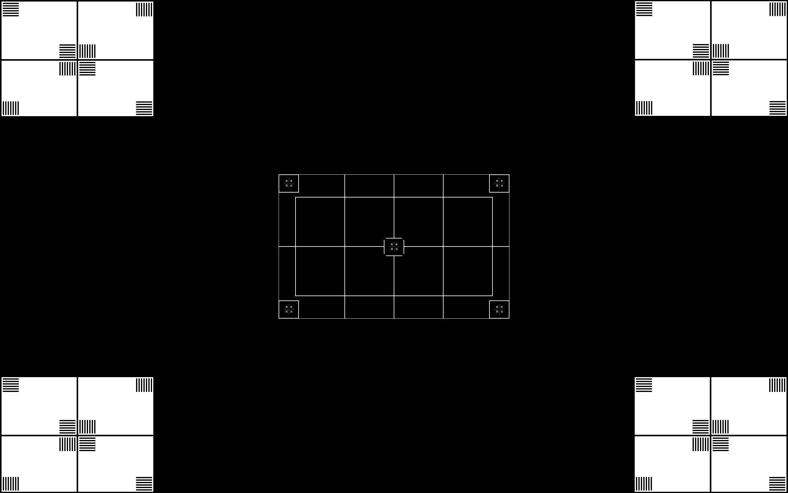
This is the test pattern (1 bit, 1600 x 2560), I attempt to display in a pattern on-the-fly mode:

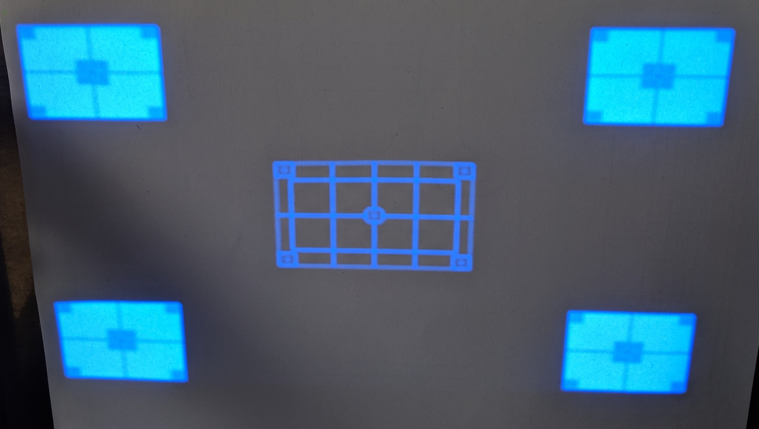
It works as intended, if I use DLP LCR6500 & LCR9000 GUI 4.0.1:

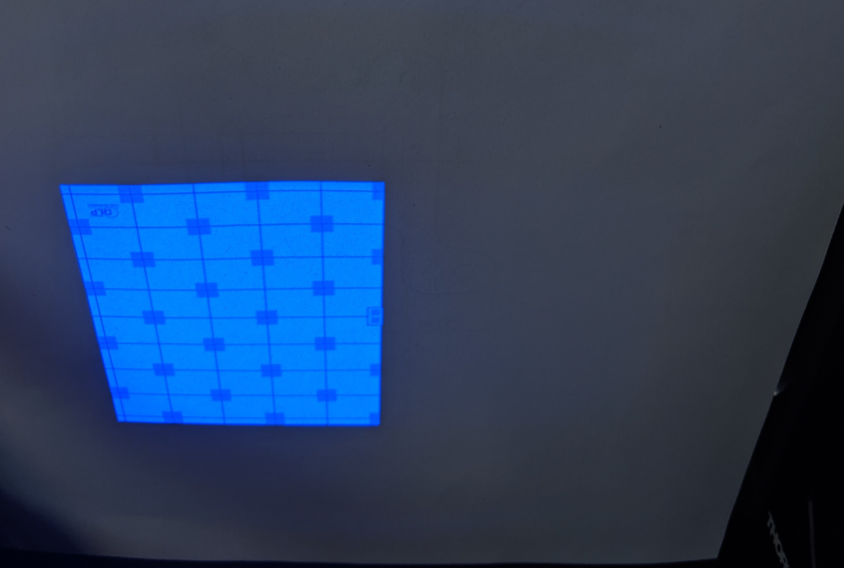
The problem arises, when using PyCrafter6500 package (https://github.com/csi-dcsc/Pycrafter6500) (modified for python 3 and for the required image size):

The projector displays only half of the pattern (on the right), while on the left side the default startup pattern is displayed:

What are the reasons of such a behavior and how this problem can be fixed?

  • Hello Roman,

    For testing purposes define some constant (lets say α) and insert a time.sleep() α between each python command to see if it is a timing issue.

    Fizix

  • Hello Fizix,

    I had already a time.sleep(0.1) after each command that modifies a state of the system. This time, I went even further, and additionally introduced time.sleep(0.5) after each data packet is sent to the device.

    I also added an additional 'Configure LUT' command (0x1A31) right after 'Define LUT pattern' command (0x1A34) as you suggested in response to one of my other questions in this forum.

    In the end, it did not help. So let me go a bit into details of what's going on.

    To simplify debugging, this time, I try to display an empty image, represented as a 3d numpy array of a size (1600, 2560, 3) (height, width, 'depth'): image = np.zeros((1600, 2560, 3), dtype = np.int).

    I attached a log file, which should reveal the details of the trial:

    1. After initializing the USB device, I go through a standard check-up routine: I query hardware status, system status, main status, power mode, display mode, DMD mode and state, sequencer status, LED outputs, LED currents. Here is a summary of the initial system state:

    2. Then I stop pattern sequence (0x1A24, data 0x00) and set pattern on-the-fly mode (0x1A1B, data 0x03).

    3. Then I define LUT pattern (0x1A34) with the following payload (byte-wise):

    - 0,   0,                 # index: 0

    - 64, 66,  15,       # expose: 1_000_000 us

    - 113,                   # '01110001'  'Continue running after previous pattern', 'LED output: White (Blue + Green + Red)', 'Bit-depth 1', 'Clear pattern after exposure'

    - 0,   0,   0,           # dark time: 0 us

    - 1,                        # Disable trigger 2 output for this pattern

    - 0,   0                   # Image pattern index: 0, bit position in the image pattern: 0

    4. Then, I configure LUT (0x1A31) with the following payload:

    - 1,   0,                  # Number of LUT entries: 1

    - 0,   0,   0,   0      # Infinite number of times to repeat the pattern sequence

    5. Then I initialize Pattern BMP Load (0x1A2A) qith the following payload:

    - 0,   0,                 # image index: 0

    - 180,  37,   0,   0 # Number of bytes in the compressed image including the 48 byte header: 9652

    6. Then I execute Pattern BMP Load (0x1A2B). I will talk about payload later below.

    8. Then, I configure LUT (0x1A31) once again with a similar payload as in step 4 (as you suggested, but even if I execute this command once, the outcome is still the same).

    9. Then I start Pattern Sequence (0x1A24, data [2]) and see the same 'half-image' effect:

    The left side represent a default pre-stored pattern, The right side is just a half of the empty image which I attempt to display.

    10. Then I query system status again:

    11. Finally I stop pattern sequence (0x1A24, data [0]).

    If i didn't screw up defining and configuring the LUT pattern, I guess the problem might as well be in the encoding algorithm. Instead of going through the code which is not trivial to grasp, I suggest to take a look on the payload of the  Pattern BMP Load command (step 6) to check if the image was encoded according to the rules of the Sections 2.4.2 (Image Header) and 2.4.3 (Pattern Image Compression) of the Programmer's Guide.

    But prior to that, I should say how the command was transferred to the device:

    - The image data including the header was 9652 bytes long. It was split into 19 packets (each containing 504 bytes of image data) and 1 last packet with a size of 76 bytes.

    - Each of this packets was 'prefixed' with four Header Bytes, two USB command bytes (0x1A2B), and two bytes defining the number of image data bytes in the packet (according to the definition of the 0x1A2B command). Thus, each packet (except for the last one) had to be transferred within a message containing 512 bytes.

    - Each of these 512-bytes messages were sent within 8x Multi-Transfer Transaction (64 tytes 8 times). The last message (84 bytes long) was sent within 2x  Multi-Transfer Transaction

    Let's take a look at the encoded data (int type):

    ### Image header (48 bytes):

    - 83, 112, 108, 100,                  # Signature bytes: 53 70 6C 64

    - 0,  10,                                       # Image width: 2560

    - 64,   6,                                      # Image height: 1600

    - 180,  37,   0,   0,                      # Number of bytes in the encoded image data: 9652

    - 255, 255, 255, 255, 255, 255, 255, 255,   # Reserved bytes: FF FF FF FF FF FF FF FF)

    - 0,   0,   0,   0,                           # Background color (BB GG RR 00)

    - 0,                                              # Reserved: 0x00

    - 2,                                              # Compression: Enhanced RLE compression

    - 1,                                              # Reserved: 0x01

    - 0, ..., 0                                      # Reserved: 21 of zero bytes 0x00

    ### Image data:

    # Encoding the first row (7 bytes):

    - 128,  20,   0,   0,   0,              # Repeat the following pixels 2560 times (2-byte encoding): (0, 0, 0) .

    - 0, 0                                         # (End-of-Line Command)

    # Encoding rows # 2 - 1599 (1598 x 6 bytes =  9588 bytes):

    - 0, 1, 128,  20,                      # Copy 2560 pixels from previous line

    - 0, 0                                         # (End-of-Line Command)

    # Encoding row # 1600 (9 bytes):

    - 0, 1, 128,  20,                      # Copy 2560 pixels from previous line

    - 0, 0                                        # (End-of-Line Command)

    - 0, 1, 0                                    # (End-of-Image Padding)

    So in total, 9652 bytes were needed to encode an empty image of a size 1600 * 2560. Since the number of bytes was a multiple of 4, no padding bytes were added (as advised in the Note in Section 2.4.3.2.1).

    With all that said here, could you please advise what else can be done to find out how to fist the problem of displaying only a half of the image.

    ID_00002_Log_file_191009113708_f125_b2.log

    Regards,

    Roman

  • Hello Fizix,

    Unfortunately, it didn't help to resolve my issue. Please see the details below. The log file is in the end of the message.

    Regards,

    Roman

  • Hello Roman,

    I have no insight to what your py scripts are actually doing.  Are you initializing both the master and slave pattern memory?  Are you sending pattern data to both the master and slave?  I am referring to § 2.4.4.4.1 Initialize Pattern BMP Load and § 2.4.4.4.2 Pattern BMP Load.

    Specifically are you writing to USB 0x1A2A and 0x1A2C - Init Load and to USB 0x1A2B and 0x1A2D - Load? 

  • Hello Roman,

    I believe we resolved this in another thread.

    Fizix

  • Hello Fizix,

    Indeed, that was a mistake of mine to initialize load and upload image data to the master controller only.

    This issue is resolved. Thanks for your help.

    Regards,

    Roman