Other Parts Discussed in Thread: DLPC900,
I'm trying to implement Run-Length Encoding according to section 2.4.3 (Pattern Image Compression) of the DLPC900 Programmer's Guide (Rev. E). Even thought it looks quite straightforward, I face the following problem.
After implementing RLE encoding of the test pattern, I followed the standard routine of displaying the image in pattern on-the-fly mode (according to the Section 5.3 (Pattern On-The-Fly Example) of the DLPC900 Programmer's Guide (Rev. E):
- Stop running the previous pattern (1A24)
- Set on-the-fly pattern mode (1A1B)
- Pattern LUT Definition (1A34)
- Initialize Pattern BMP Load (1A2A)
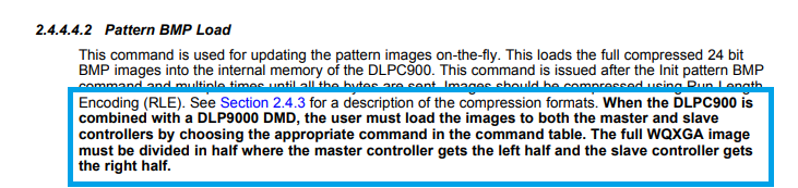
- Load compressed BMP Data (1A2B)
- Configure Pattern LUT (1A31)
- Start running the pattern (1A24)
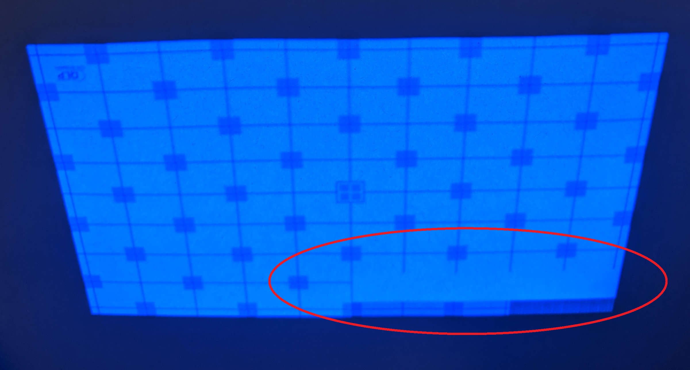
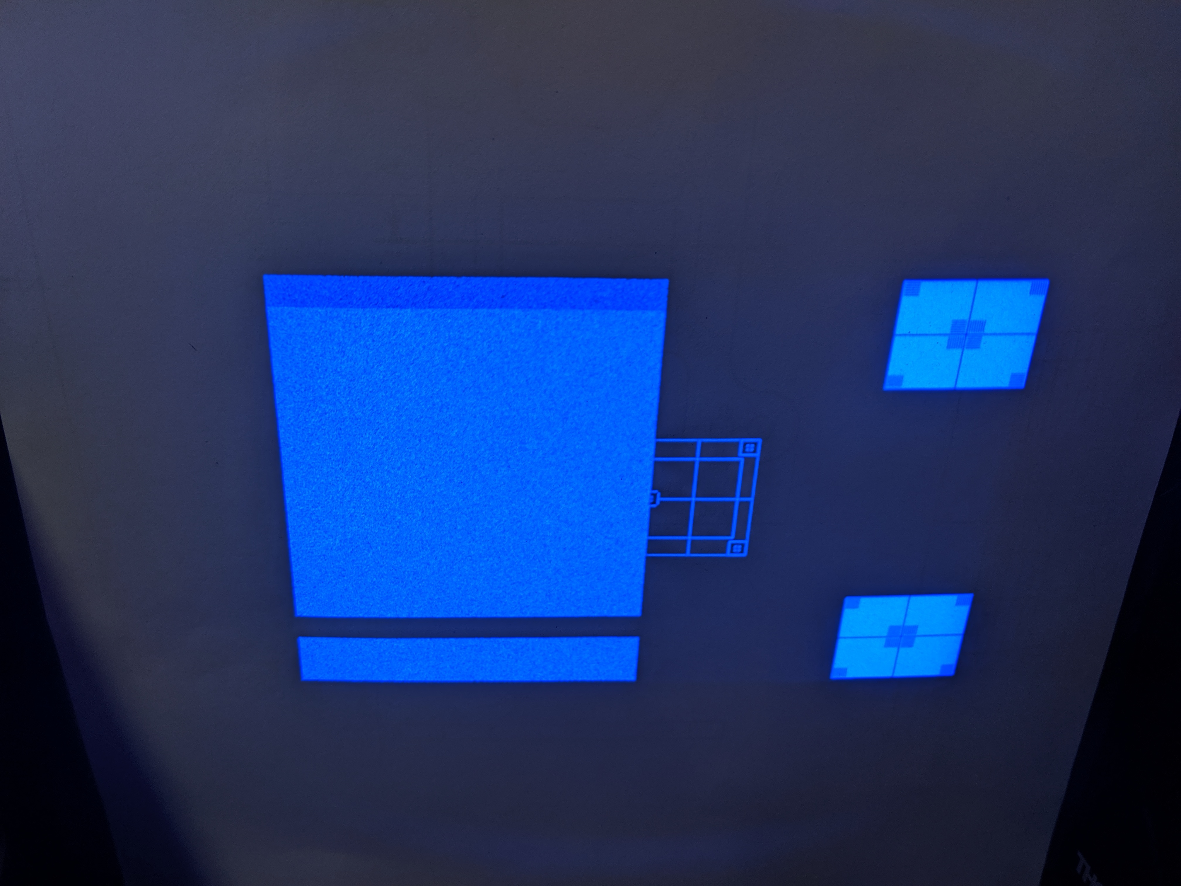
Data transmission is done with no errors generated. The device, first, responds as intended: it stops displaying the default pattern. Then, after a few seconds of data encoding and transfer, it displays the pattern. However, instead of the desired one, the projector displays the default pre-stored startup pattern.
Displaying the image in the on-the-fly pattern mode using DLP LCR6500 & LCR9000 GUI 4.0.1, works totally fine.
I assume, the problem is in the encoding logics. Instead of me posting here the code snippets, I'd like to confirm with you a couple of aspects of the RLE compression according to the section 2.4.3 (Pattern Image Compression) of the DLPC900 Programmer's Guide (Rev. E).
1. According to the Table 2-98. RLE Control Bytes: The control byte n > 0 defines the number of times the next RGB pixel has to be repeated. Let's say, I want to repeat the next RGB pixel 2560 times. This value cannot be represented by one byte. How to handle this situation? (Should these 2560 identical pixels be compressed as: 255 RR GG BB ...<8 more times>... 255 RR GG BB 10 RR GG BB? Or is there a smarter trick, such as two byte encoding? The manual does not address this scenario for the Run-Length Encoding)
2. Could you please confirm if the End-of-Line padding should be '00 00 00' and the End-of-Image Padding '00 01 00 00 00 00 00 00 00 00' (as mentioned in the Table 2-99. RLE Compression Example)?
3. Could you please refer to any sources that explicitly demonstrate the algorithm of RLE encoding (or Enhanced RLE) according to the Control Bytes definitions and examples in the DLPC900 Programmer's Guide? I tried to use the logic from the Pycrafter6500 package (https://github.com/csi-dcsc/Pycrafter6500),
Please let me know if I should provide more information to the problem described here.