This thread has been locked.

If you have a related question, please click the "Ask a related question" button in the top right corner. The newly created question will be automatically linked to this question.

lightcrafter static image bmp gamma

Other Parts Discussed in Thread: DLPC300

I am currently uploading 24-bit BMP files to the lightcrafter evaluation module.   Does the lightcrafter kit apply a gamma correction when displaying bitmaps with the projector?  Basically, is the time the DLP mirrors are on linearly correlated with the 8-bit values in the bitmap?  Or is there some other function that maps the DLP mirrors "on time" to the values in the bitmap (presumably a gamma correction function)?  If it is a gamma correction function, what value of gamma is used?

Thanks 

  • Hi Ray Wilhelm,

    Apologize for delayed reply to your query.

    Welcome to DLP & MEMS forum.

    I presume you are asking question when LightCrafter(TM) is configured in Display Mode = Static Image. And then you are uploading a 24-bit BMP image from 'Static Image' section under 'TestPattern/Image' tab. Yes, in this mode, the de-gamma correction is applied. So you should NEVER use this mode for checking for Linear Correlation of DLP mirror with respect to input 8-bit value of the input image. The degamma correction resemble 'S' curve so I don't have direct degamma number to share with you.

    Attaching the curve plot for your better understanding.

    Note, the DLP Mirrors are linearly correlated when LightCrafter set to Display Mode = Pattern Sequence where you can program the patterns and display them at user selectable 'exposure timings' and frequency. Features like degamma correction and other image enhancement functional blocks inside DLPC300 will be turned OFF by DM365 processor. So, DM365 takes care of ensuring 'linear correlatable' data path is maintained whenever user selects Display Mode = Pattern Sequence.

    Regards,

    Sanjeev

  • Dear Sanjeev,

    About this linearity in terms of grayscale value in 'Pattern Sequence Mode':

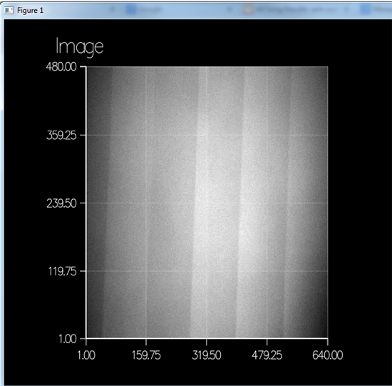
    My measurements indicate that when a shorter exposure time than the maximum possible exposure time (8333µs) is used in pattern sequence mode, the grayscale does not evolve linearly, but with sudden jumps. Please see attached image for example, here a regular 8 bit ramp was displayed going from 0 on the left to 255 on the right. Projected with the red LED, bands appear as can be seen in the image. These bands dissapear when the full 8333 µs exposure time is used.

    Is there an internal mechanism that could account for this behaviour? I'm not sure what the reason for this is: are the micromirrors updated sequentially going from left to right?

    Thanks,

    Sam

  • No. Pulse width modulation. http://focus.ti.com/download/dlpdmd/141_hornbeck.pdf
  • Thanks for that paper, Curtis,

    From it, I gather that the mechanical switching time is ~15 µs. So this cannot account for those types of jumps that I'm seeing at exposure times of 3-4000 µs... correct?

    Would there be any other mechanism that might be the reason for this behavior that you know of?

    EDIT: citing the paper: " These artifacts can be reduced to negligible levels by a “bit-splitting” technique [26]. In this technique, the longer duration bits are subdivided into shorter durations, and these split bits are distributed throughout the video field time. DLP displays combine pulsewidth modulation and bit-splitting to produce a “true-analog” sensation, but with greater accuracy and stability than can be achieved by analog projection systems.

    Could this be the reason for the vertical grayscale blocks? Because of the bitsplitting, I will only record parts of the longer duration bits, while I might get the entire shorter duration bits? If so, this would mean that not all bits are subdivided into equally as many parts...

  • No. As far as I know current DMDs are not doing bit splitting. When you look at this: https://commons.m.wikimedia.org/wiki/File:Zyklus_DMD.svg (Unfortunately in german). What happens if you stop the camera exposure before bit 4 is fully displayed? What will the image look like? Note that the abscissa is time.
  • Very interesting graph, from this I gather that the total "video time" of a DMD mirror is divided into uneven timeslots, that only when the timeslots are all added together will they produce the correct grayscale value. So if the camera exposure time is stopped before bit 4 is displayed fully, I lose a lot of light... correct?

    In this case, I should always use the exact same camera exposure time as the DMD cycle time?

  • Yes. To be correct the camera exposure has to be a multiple of the DMDs cycle time. C.
  • Great, thanks for your help!