This thread has been locked.

If you have a related question, please click the "Ask a related question" button in the top right corner. The newly created question will be automatically linked to this question.

How to enable DLPC300 BIST

Other Parts Discussed in Thread: DLPC300, TPS65070, AM1806

Currently we've problems with some PCBs (proprietary desing) where DLPC300 is just displaying TI Splash screen. On the screen there written "Booting...".

However, while trying to find the issue I found "mDDR Memory BIST Status Register (I2C: 0x9B)" register in the Programmers I understand there is something existing like a selft-test but it seems to be disabled. BIT 1 of the register never becomes 1. Programming Guide: "0= BIST is in progress (if enabled)". So how can I enbale.

I assume the PIN "TEST_EN" (A9 / "Reserved for test") is used for enabling the self test. Can you confirm that? On the PCB it is hard wired to ground.

Otherwise, what does indicate when DLPC300 is displaying splash screen continuously.

Thank you advance for any help, because currently I'm completely blind.

Kind regards,

Roland

  • Hi Roland,

    Thanks for your question and welcome the DLP Forums!

    I'm not sure that the BIST function you found will assist you in your debugging, I believe that is intended for the mDDR specifically.

    Can you describe the issue you are seeing in a little more detail? From your post, it seems that the device is stuck booting. Are you monitoring a UART output or is "booting..." what is being displayed on the DMD?

    It would also be helpful to understand the general block diagram of your system. Do you have an FPGA or apps processor on the board? Your issue sounds similar to an issue we have on our Lightcrafter EVM and the two most common fixes are to switch to a power supply which can handle more current draw and to reload the FW of the device.

    Thanks,
    Paul
  • Hi Paul,


    thank you very much for the quick reply.

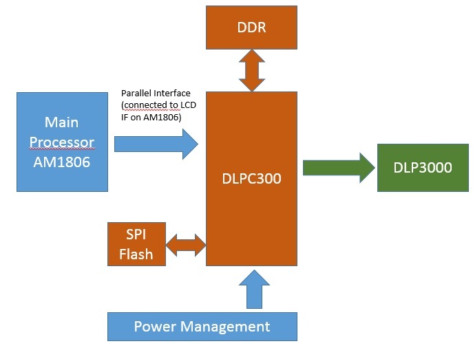
    First of all, I took the project over and there is - as usual ;-) - not that much of documentation. However, see bleow the block diagram I've created (sorry for the poor ppt).

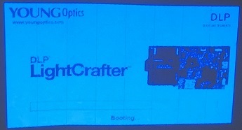
    The text "Booting ..." is displayed on the DMD. There is also "YOUNG Optics DLP Light Crafter", an Evalboard and a progress bar displayed.

    You've metnioned UART: Is there a UART available on the DLPC300 for sending debug information? I didn't find one.

    Regarding the possible problems:

    1. Power supply. The PCBs work in general. We've received a view PCBs showing the problem is described above. So I think there is no need to switch to another power supply. While debugging I've measured all connected voltages and all are ok. Anyhow, is it possible that a problem with power supply (TPS65070) could cause such problems.
    2. Device-FW. Is the firmware of the DLPC300 stored on the SPI flash or device memory? Where can I get the firmware? How can I update it (is there an app note)?

    Even the mDDR is not the problem in this case, the BIST function might be useful for field diagnostics. The mDDR is not connected to the AM1806 which means it cannot be checked. So it would be nice if this feature was available.

    Kind regards,

    Roland

  • Hi Paul,

    in between I did another test. I've exchanged the SPI boot flash of a PCB that is showing the effect with another one that works fine.

    Result:
    Both PCBs don't change their behaviour, meaning the good one is still good and the problem one still shows splash screen. So, if meant with "reload the FW of the device" to write the boot flash again, this seems not to be the solution.

    Kind regards,
    Roland

  • Hi Roland,

    Thanks for the additional information. Roughly what percentage of your PCBs are showing this issue?

    To clarify my power supply comment, I was referring to the bench top supply or wall wart that you are using as the main system supply. With our EVM, the most common problem we see is customers trying to use a 1 or 2A rated supply when really they need 3A or more for reliable operation.

    The FW for the DLPC300 is generally stored on an external SPI flash, not on the device directly. You can find the FW here: http://www.ti.com/tool/DLPR300
    As far as updating it goes, that will depend on how your system was designed and our only guide on how to update the FW is related to the EVM and can be found in Section 2.13 of the Lightcrafter User's Guide: www.ti.com/.../dlpu006e.pdf

    The Lightcrafter EVM features a UART output from the DM365 apps processor, so probably not applicable in this case. I understand now that you're actually seeing the loading screen projected.

    I'll take a look and see if I can get more detail on the mDDR function.

    A couple questions for you:
    * What software is being run on the AM1806? Perhaps reloading that software would be worth doing just to eliminate another possibility?

    * Are there any other symptoms besides getting stuck?

    Thanks,
    Paul
  • Hi Paul,

    thanks for your help. Regarding your questions:

    • The AM1806 runs our custom application. The low level parts seem to be taken from the EVM (there are TI headers inside). I'm reloading the software all the time 'cause I'm actually busy with imporvements and code cleanups. The problem is really tight to the PCB and is reproducible with older and newer firmwares as well. We receive the boards from an external supllier and I try to find the root cause in order to improve the test sequence on their side. The number of defect PCBs is below 10% (unfortunately I've got no concrete numbers).
    • Very rarely there are problems with AM1806 DDR2 RAM. Others are showing black screen instead of splash screen. Actually there are no other defects.

    I general I'm abale to check all parts connected to the ARM. My problem is how to ensure that the parts connected to DLCP300 are wroking properly.

    Kind regards,
    Roland

  • Hi Roland,

    It might be useful for you to take a look at the EVM schematics for reference if you haven't already. They can be found here: www.ti.com/.../dlp3000-c300ref

    This will give you a good starting point on looking at how the DLPC300 is connected and seeing if there are any major differences or sticking points.

    -Paul
  • Roland,

    The BIST test just test the DLPC300 mDDR. This mDDR stores the buffer data that is used by the DLPC300 to send to the DLP3000. Since you are getting a splash image, the mDDR buffer seems to be storing the correct data. The next steps are to figure out if there is an issue sending commands to DLPC300 through I2C, streaming an image to DLPC300 through the parallel interface. Here are a few things you can do to test. If you are not exactly sure of the right steps, connect an I2C bus analyzer to the LightCrafter I2C bus and capture the stream of commands when using similar settings in the LightCrafter GUI.

    • Verify I2C connection by reading the main status register. Section 2.1.2 of the DLPC300 Programmer's Guide
    • To verify the DLPC300 to DLP3000 connections, load an internal test pattern by issuing the appropriate I2C commands detailed in Section 2.2.3.1 and 2.2.3.2.1 of the DLPC300 Programmer's Guide
    • Then verify that loading from SPI flash is working properly by loading a splash image.
    • Then verify loading from parallel port (external video sequence) and sending the appropriate data from AM1806

    If the video you see is shown in only one color, the sequence is not progressing. Check that the SPI connections to the DLPC300 and LED connections are good.

    If the video has fixed vertical lines, that is typically a problem with one of the RGB signals between your processor and DLPC300.

    Ensure that the proper timing with VSYNC, HSYNC, and pixel clock are maintained. Since you are not using the FPGA, a 60 Hz VSYNC and appropriate HSYNC and PCLK might be required to advance the sequence.

    In the LightCrafter, there are four splash images that the MSP430 loads and progresses until the DM365 boots linux and takes over. The UART output is from the DM365 and part of our linux package. Also, note that the DM365 code sends two 16-bit parallel port packets and the FPGA combines them into a 24-bit packet for the parallel port of the DLPC300. I believe the LCD Controller of the AM1806 is 16-bit, so you might need to enable RGB565 mode on the DLPC300 that is different than the RGB888 used in LightCrafter.

    The LCD Controller should be programmed for raster mode in 608 x 684 mode or matching the resolution settings of the DLPC300. 

    Best regards,
    Pedro

  • Hallo Pedro,

    thanks for alle the information. Maybe it was not clear, that everything runs in general. I've got the problems only with some of the PSBs. Prior to opening this therad I've checked nearly everything you've listed above, except the test pattern (I2C, CLOCK, VSYNC, HSYNC, voltages, boot flash). The application is running correctly since years.

    In between, I've changed my application that it displays one of the test patterns after bootup. PCBs that displayed a "bootup screen" before have not changed their behaviour. The display doesn't change no matter what I'm programming. I've also tested the modified appilcation with the "good boards" with the result that test pattern is dispalyed as exepected. When I read everything above: this looks to me like DLCP300 is not booting. Correct?
    If so: what can be the cause? We had exchanged the DLPC300 at 3 of our boards without an effect => DLPC300 ist OK. I've recorded SPI traffic of flash and compared good and defect boards => no difference.

    Finally, could you please give me the information whether the BIST is available for customers or not? I would like to make clear that a NOT is no problem for me. I just want a reliable information (and of cause how to activate it in case of YES). I aware of that my current problems are not related to the RAM test. So this information is just additional knowledge for me.

    Thank you in advance and kind regards,

    Roland

  • Roland,

    Yes, it seems the DLPC300 has not completed booting. I am assuming the PLL is properly running and that the crystal is oscillating properly. Given that there was a SPI traffic from the DLPC300 SPI flash, it seems the DLPC300 started reading the SPI flash, but failed in one of the following areas:

    • SPI flash code was not read properly by the DLPC300. This might be related to SPI flash interface timing issue or noise on those lines. 
    • I2C commands not understood. This might be related to a stronger or weaker pull-ups on I2C lines than necessary. If using 10K pull-ups, try changing them to 4.7K, or vice versa.
    • Incorrect I2C address due to floating or incorrectly pulled I2C_ADDR_SEL pin. 
    • Problem with VCC_INTF supply levels or noise.
    • Noise on reset pin.
    • Noise on park pin.
    • Damaged DLPC300.

    As far as the BIST, the DLPC300 performs an auto-initialization routine that runs BIST before displaying the splash screen. The register indicates the result of the BIST test. Upon completion of the auto-initialization, the INIT_DONE signal goes low. If this signal is pulsing, there was an error in the auto-initialization.

    Best regards,
    Pedro

  • Hello Pedro,

    thanks. This gave me some more background.

    I'll keep this as answered, even it doesn't answer the original question regarding BIST. From the following thread I've got the information that BIST was disabled for boot time reasons.

    https://e2e.ti.com/support/dlp__mems_micro-electro-mechanical_systems/advanced_light_control/f/850/t/367826#1833946

    Since status bit in 0x9B is never set (even on PCBs taht are working properly) I assume this assertion is correct. The original question was if I can enable it or not. (please see upper posts of this thread).

    If you could answers this question I will finally consider it as answered.

    If I'll find my issues I will add it to this post.

    Thanks again and best regards,
    Roland

  • Roland,

    The post is correct, sorry about that. On DLPC300 the BIST is not invoked at auto-initialization to reduce the firmware footprint and boot-up time. There is no user access to the BIST controller, so it is unavailable.

    Best regards,
    Pedro