This thread has been locked.

If you have a related question, please click the "Ask a related question" button in the top right corner. The newly created question will be automatically linked to this question.

DLP4500: Cannot work without focusing optics and led.

Part Number: DLP4500

Hi,

I removed the focusing optics and LED to let parallel laser ( 532 nm ) enter (from green LED position), and load a specific pattern according to this http://www.ti.com/general/docs/video/watch.tsp?entryid=0_mm7qq7th . But I cannot see any change of the laser out from the light engine. Does anyone know the reason? 

Thanks,

Mei

  • Hi user,

    Can you confirm what version of the firmware you are using along with the GUI version? The one shown in the video is out of date. Were you able to display patterns before changing the illumination? Are you seeing anything projected or is there no image at all?

    Thanks,
    Kyle
  • Hi Kyle,

    Thanks. The firmware version is DLPR350PROM_v3.0.0 and the GUI version is v3.1.0. I can display some rectangles by pattern sequence function (without loading image) before I removed light engine. I can see some light from the exit, but it did not change when I loaded pattern. Should I add some optics behind the exit port? I am sorry I found the incident position is Red LED position not the Green one.

    Thanks,

    Mei
  • Hello Mei,

    It may be very difficult to see the image change without optics. I would try to see if you can see the DMD mirrors change without illumination (i.e. look at the DMD directly, send patterns, and see if the mirror responds). If you can see the mirrors change then you know that is operating correctly and it is an issue with the optics. Also you may want to try the firmware v3.1 http://www.ti.com/tool/dlpr350

    Thanks,
    Kyle
  • Hi Kyle,

    Thanks.But I can not see the DMD mirrors, I did not remove the TIR prism. Is there any method that I can see the DMD mirrors? If I remove the TIR prism, can I get the same light path as the original when I put it back?  I knew the inside view according to this post https://e2e.ti.com/support/dlp__mems_micro-electro-mechanical_systems/advanced_light_control/f/924/t/278008#pi239031350=2

    Thanks,

    Mei

  • Hello Mei,

    It sounds like you removed the projection optics as well as the light engine, but not the TIR prism assembly.  I would leave that intact.  You should be able to look DMD surface (even if the µ-mirrors are too small to see individually).  

    With the laser off shine a small flashlight into he opening you are sending he laser down (i.e. the RED LED opening) and send a slowly alternating all on (white) and all off (black image) pattern.  You should be able to see the appearance of the DMD surface change.  Depending on your vantage point it should go from lighter to darker or the reverse.

    If you do not see the image changing, then there may be a more fundamental issue.

    Also if you haven't, please reference this video:  https://www.youtube.com/watch?v=POEKXTIH3Y8

    Fizix

  • Hi Fizix,

    Many Thanks. But I still can not solve my problems and have some questions,

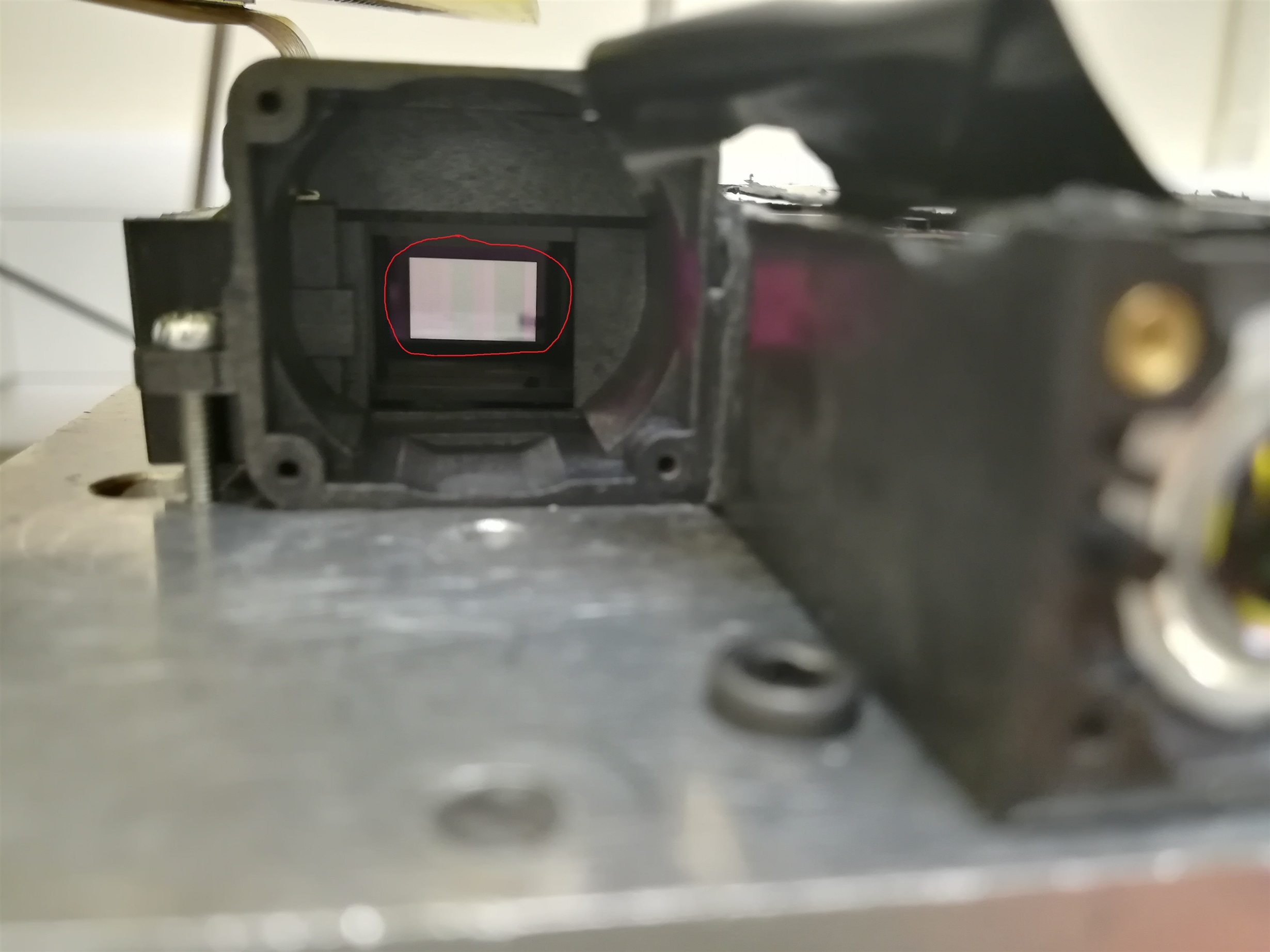
    1. The mirror in the red circle is DMD as the photo shows? DMD is not on the side, I think it should be on the side as this post explains  https://e2e.ti.com/support/dlp__mems_micro-electro-mechanical_systems/advanced_light_control/f/924/t/278008#pi239031350=2 There are two strips on the mirror when it is on flat status.

    2. I set the parameter as the following picture shows, is it ok? I removed the LEDs, there is no light from LED actually, but it seems I have to choose one color to set the sequence. The image pattern is from 3 same 8-bit images.

    Thanks,

    Mei

  • Hello Mei,

    I will let comment on point one as I think he may known better than I.

    However, for point 2 I would personally recommend that you have two 1-bit white patterns. The first white pattern should load an all white image and the second white pattern should load an all black image. This will effectively change the mirrors from full on and full off. If Fizix is unable to get back to you I will keep investigating on my end.

    Thanks,
    Kyle
  • Thanks Kyle.

    I tried to use two 1-bit images to create an output image and get a firmware, but when I uploaded the firmware, I got an error 'Unable to read flash manufacturer ID'. I tried to power off and power on, it did not work this time. This error appeared before, I solved it by clicking "Reset System" button in GUI and powering off and powering on some times. My computer is windows 10 pro.

    Thanks,

    Mei

  • Hello Mei,

    Did you modify any of the settings of the GUI source code? And could you confirm this is still an error with the latest, unmodified flash image (I believe it should be 3.1). After that, try adding the two images (or rather 1 24-bit image of which you will display using 2 1-bit patterns) to the flash using the GUI.


    Thanks,

    Kyle

  • Hi Kyle,

    It is still an error, even if I reinstall the GUI. I did not change any setting before I created the new firmware with two 1-bit images. It happened suddenly.

    Thanks,

    Mei
  • Hello Mei,

    Does it ever upload successfully with the newly created firmware? Also can you successfully upload a regular 3.1 firmware? Can you confirm you are using 3.1.

    Thanks,
    Kyle
  • Hi Kyle,

    Before this error, I could get the 'Download completely' box with my own firmware (from three same 8-bit images), but now, I cannot even upload the firmware with three 8-bit images nor the regular 3.1 firmware. My GUI version is v3.1.0 and the regular firmware is DLPR350PROM_v3.1.0.

    Thanks,

    Mei
  • Hi Mei,

    Could you try flashing the device by populating jumper J30 and update the flash via USB. This is shown on page 4 of www.ti.com/.../dlpu017a.pdf. If that still doesn't work you will need to follow the entire guide of how to fix a corrupted firmware image with the JTAG connector.

    Thanks,
    Kyle
  • Hi Kyle,

    I populated jumper J30 with a 2.54mm jumper (I cannot find a 2 mm jumper now), it still does not work. I do not have JTAG connector, what should I do?

    Many Thanks,

    Mei
  • Hello Mei,

    Ensure that there is a proper connection on the jumper if you are using the wrong size. You may have to temporarily solder wires together to ensure a connection is being made.

    Are you not ever able to upload the new firmware now? If you have confirmed the jumper is properly populated, and you are using the most up-to-date firmware and GUI then the only other recommendation is using the JTAG cable to re-flash the image.

    Thanks,
    Kyle
  • Hi Kyle,

    I solved that problem by uninstalling the "USB composite device" and reinstalling itself after a hardware change scan or unplugging and replugging in Lightcrafter USB cable sometimes. I am not sure which one worked, but I can upload firmware yesterday. However, when I turned on the device today, it cannot connect the GUI (the "USB composite device" can be found in device manager). I did not change anything, only power-off and power-on.

    Thanks,

    Mei
  • Hi Mei,

    Are you able to try connecting to the Lightcrafter 4500 on a different computer? That well help us determine if it's an issue with the unit or with the PC.

    Thanks,
    Kyle
  • Hi Kyle,

    The Lightcrafter 4500 can be connected to another window 10 computer (laptop, same GUI) and upload firmware, but it is not possible for me to change my computer as some other hardware. What should I do on my computer?

    When I choose Video Mode, the Seq. Running light is green, I forgot is this normal?

    When creating images (like using two 1-bit images or three 8-bit images), what should I do about choosing the bits position in the destination file? When creating sequence under pattern sequence mode, what should I do about choosing the pattern(e.g. G0-G8,R0-R8,B0-B8)? I am confused now even after watching the guiding movie linked before...

    Thanks,

    Mei
  • Hello Mei,

    Unfortunately if you have already uninstalled the driver and GUI and then have done a fresh reinstall I can't think of much else short of reinstalling Windows. Since it does work on another computer at least we can confirm the 4500 is operating correctly. Perhaps someone on a Windows form would have an idea about the driver.

    And yes, this sounds correct. As far as the bitplane question have you read the user's guide? www.ti.com/.../dlpu011 If you still have additional questions about the bitplanes please feel free to make another question so we can properly organize the forms (it just makes it easier for other people to find answers later).

    Thanks,
    Kyle
  • Hi Kyle,

    I will try other way to this question. If I have other questions, I will make a new post. But can you remind Fizix to look at my question 1 list before about which is the DMD mirrors?

    Thanks,

    Mei
  • Hello Mei,

    With regards to your original question I discussed it with another coworker. The DMD is attached to the flex cable as you impliedand you are seeing some of the optics. However, you should be able to see some light coming through with the mirrors on and then no light with the mirrors off if you are continuously shinning the flashlight through the LED opening. If you aren't seeing any change it sounds like something is broken with the DMD. If it works then there might be something incorrect with the laser setup.

    Thanks,
    Kyle