This thread has been locked.

If you have a related question, please click the "Ask a related question" button in the top right corner. The newly created question will be automatically linked to this question.

DLPC350 I2C1_SCL is sticked low.

Guru 10570 points
Other Parts Discussed in Thread: DLP4500, DLPC350, CC3200-LAUNCHXL

Hello,
I am using DLPC350/DLP4500 in our system.
Sometimes, we can observe the phenomenon that I2C1 SCL is sticked low.
Once it have been occured, DLPC350 can not response to any commands from other I2C master.
I would like to ask you whether this issue is reported before.

Note:
Currently, we can observe this issue on our custom board.

Best regards, RY

  • Hello RY,

    We would like to know after which command you are noticing such behavior. We highly suspect it should be coupled with the certain sequence or order of commands sent over the bus.

    We have seen you are running at 400KHz can you also reduce the clock to 100KHz let us know if you seen any change in the behavior.

    Regards,

    Sanjeev

  • Sanjeev-san,

    I'm sorry for my late reply.
    I could reproduce it in LightCrafter4500.
    I2C1_SCL is sticked low in a few seconds when I send "Validate Data Command(I2C:0x7D)" repeatedly.
    The sequence is below:
      S 34 FD 00 P
      S 34 FD 00 P
      S 34 FD 00 P
      S 34 FD 00 P
      ...

    Can I have asking whether there is any violation in my sequence?

    Description of 0x7D is below in DLPC350 PG(dlpu010c).

    Best regards, RY

  • Hello RY,

    Compared to the rest of the commands the Validate command 0x7D takes time to execute validation procedure. During this time it block any further communication.

    We highly recommend you to read the Validation command response and then issue next validation command if you would like to.

    So sequence should 

    S 34 FD 00 P

    (delay 1ms)

    S 34 7D 00 P (Issue command to read the response)

    S 35 0xXX 0xYY P //Read the response, here repeat the sequence until you see 0xXX = 0x01 or 0x03. 0x03 indicates command didn't execute properly, so go back to issuing validate command, if 0xXX = 0x01 then read and analyze the validation status 0xYY. 

    Let me know if you still face any problem.

    Regards,
    Sanjeev

  • Sanjeev-san,
    Thank you very much for your advise.
    Although I checked your sequence, the issue happend.

    I did two examinations:
      exam-a) In video display mode (I2C: 0x69 = 0)
        The issue have never happend.
     
        Note: Status byter returns always 01. 00 and 03 has never returned.


      exam-b) In Pattern display mode (I2C: 0x69 = 1)
        When I tried following sequence, I could observe the issue in a few minutes on LightCrafter4500.
       
        Sequence:
          S 34 E9 01 P // write (I2C:0x69) = 1

          S 34 FD 00 P // write (I2C:0x7D) = 0
          (delay 1msec)
          S 35 7D 00 P // I could read (I2C:0x7D) = 00 or 08

          S 34 FD 00 P // write (I2C:0x7D) = 0
          (delay 1msec)
          S 35 7D 00 P // I could read (I2C:0x7D) = 00 or 08
          .. repeat ..

          Note: When status byte returns 00, I repeat the command.
                I could observe status byte as 00 about 90-240 times each command.
                03 has never returned.

    It seems some restrictions exist in it.
    If you have more informations, please let me know.

    Can you check this?

    Best regards, RY


  • Hello RY,

    exam-a)

    There is nothing to be done at the DLPC350, in the Video Mode, the Validate Command don't perform any action. The Validate Command, begin the validation procedure only when the device is configured in Pattern Display Mode.

    exam-b)

    03 status returned only when if it failed execute the command, so in your both exam-a and exam-b the command is always getting executed successfuly so it is not returning 0x03.

    Do you mean 01 is never returned as a status byte? Only when it returns 0x01 as status byte you can interpret the Validation Status information.

    Increase the delay from 1ms to 10ms or even more, for example - give like 500ms delay and then read the status, you should see status byte 0x01.

    Regards,
    Sanjeev


  • Sanjeev said:

    Do you mean 01 is never returned as a status byte?

    Sorry. I can not really understand its meaning.
    What comments do you refer?

    Sanjeev said:

    Increase the delay from 1ms to 10ms or even more, for example - give like 500ms delay and then read the status, you should see status byte 0x01.

    When I insert delay from 1msec to 10msec, it was reproduced.
    But, when I insert delay 100msec as following, it was not happend. Thank you so much!

     Sequence:
          S 34 E9 01 P // write (I2C:0x69) = 1

          S 34 FD 00 P // write (I2C:0x7D) = 0
          (delay 100 msec)
          S 34 7D P      // Issue read command (I2C:0x7D)
          (delay 100 msec)
          S 35 XX XX P // read data from DLPC350

    I think its timing spec should be specified in the documents.
    Because, user needs it for reliable system.

    Can you let me know the minimum delay of each commands?

    Best regards, RY

  • Hello RY,

    Validation Command [0x7D] is the only command that takes more time, for rest of the commands you should be able to read response in less than 10ms time.

    Minimum delay time - What was the size of Pat LUT table used ? The easiest way would be test  for the max LUT i.e., 128 entries and you can check if 100ms returns the response.

    On different context we will be soon putting a new 2.0 firmware update for DLPC350 controller where in which we have added a new 1-bit flag in the Validation Status response. The DLPC350 would always respond and it will set this flag - '1' (saying BUSY) and clears when validation completed. So you don't need to have long wait time.

    Regards,
    Sanjeev

  • Sanjeev-san,
    Thank you for your advise.

    Sanjeev said:

    Minimum delay time - What was the size of Pat LUT table used ? The easiest way would be test  for the max LUT i.e., 128 entries and you can check if 100ms returns the response.

    I am gonna do its test.
    BTW, how many times does status byte allowed to be 01 until response returns?

    In the sticking case, status byte was returned 01 about 30-240 times.
    When I insert 100msec delay, it was decreased about 1-3 times.
    Although it did not happen any issue during our 1 hour exam, sticking might be occured during long term operation.

    I need to know what is the safe line.

    I will insert 10msec delay to other commands.
    Thanks.

    Best regards, RY

  • Hello RY,

    BTW, how many times does status byte allowed to be 01 until response returns?


    I am not following your question. Whenever status byte is showing '01' it means command is executed successfully, do mean even though status showing '01' you are not able to read the Validation response data after reading the status byte?

    Regards,
    Sanjeev

  • Sanjeev-san,

    Sorry, my explanation is wrong.
    Our customer would use new firmware 2.0.
    Thanks !!

    Best regards, RY


  • Sanjeev-san,

    DLPC350 firmware v2.0 has I2C LUT load issue :
    e2e.ti.com/.../1422708

    Since their target board has I2C but does not have USB, they can not update to v2.0.
    For reliable operation, they need to clarify sufficient waiting time during Validation Command [0x7D].
    Can I have its information?


    Here is one of my idea.
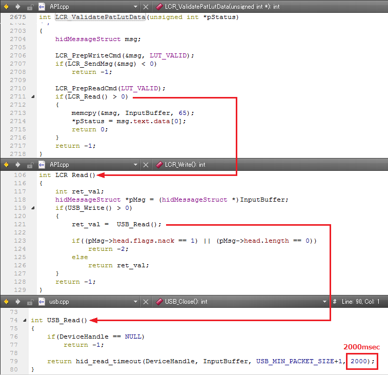
    In GUI SW, 2000msec waiting is inserted in Varidation Command by USB.
    Can I think its period is reliable for I2C operation?

    Best regards, RY

  • Sometimes, we can observe the phenomenon that I2C1 SCL is sticked low. Once it have been occured, DLPC350 can not response to any commands from other I2C master. I would like to ask you whether this issue is reported before.
    [Sanjeev] We haven't seen such issue reported by anyone so far. Does it happens only upon issuing Validate Sequence command 0x7D?

    The 2000ms is for USB protocol read packet timeout, since you are communicating via I2C i would like to know what is the delay put currently before reading the validation response?

    Regards,
    Sanjeev
  • Sanjeev-san,

    Thank you for your reply.

    [Sanjeev] We haven't seen such issue reported by anyone so far. Does it happens only upon issuing Validate Sequence command 0x7D?
    [RY] Yes. I checked it again and can be reproduced the issue in LightCrafter4500 soon.
    Also our customer have seen it in their target board.

    Could you check it in your LightCrafter4500?
    I would like to know if it is restriction of LightCrafter4500 or not. If yes, I need to know the safe delay between write and read transaction.

    "I2C1_SCL is sticked low": It will happen as following sequence.

    S 34 FD 00 P // write transaction (I2C:0x7D) = 0
    (1-10msec delay) Note: It does not happen by 100msec delay.
    S 34 7D P // read transaction (I2C:0x7D) could read (I2C:0x7D) = 00 or 08
    S 35 01 XX P
    .. repeat ..
    You can see the phenomenon that "I2C1_SCL is sticked low" from waveform.

    Best regards, RY

  • Sanjeev-san,

    Can you see the issue in your LCr4500?
    If you need more information please let me know.

    Best regards, RY

  • Hello RY,

    Have used Devasys USB-I2C box to send commands from PC, this will add the delay ~10ms b/w each I2C command, when i run this setup, in loop 20 to 30 times, i am not able to reproduce the I2C1_SCL stuck low issue. The bus is released for the next command.

    Regards,
    Sanjeev
  • Sanjeev-san,
    Sorry for my late reply.
    To reproduce, we can provide our MCU Project, or make it for other TI MCU. (e.g. for MSP430)
    Do you have any MCU environment?

    We have seen the issue using following environment.
    - CC3200-LAUNCHXL : www.ti.com/.../CC3200-LAUNCHXL
    - BeagleBone Black : www.ti.com/.../beaglebk

    Best regards, RY
  • RY,
    Let me check again. If you are not allowing a delay after issuing Validation command, it may not go through but I am pretty sure the i2c1_scl not get stuck forever.

    Is your customer having any concerns by putting delay - how about below logic?

    S 34 FD 00 P // write transaction (I2C:0x7D) = 0
    delay 100ms //Allow time for DLPC350 start validation check

    count = 0;

    while (count < 5) //for example - try 5 times. if doesn't get over exit and flag error
    {
    S 34 7D P // read transaction (I2C:0x7D) could read (I2C:0x7D) = 00 or 08
    S 35 01 XX P
    if(XX == 00) {
    return success;
    } else {
    count++
    delay 100ms
    }
    count ++
    }
    return fail;

    Regards,
    Sanjeev
  • Sanjeev-san,

    I am sorry to not respond to your comment.

    > If you are not allowing a delay after issuing Validation command, it may not go through but I am pretty sure the i2c1_scl not get stuck forever.

    I am afraid but DLPC350 can not respond forever once it get stuck until reset.
    In order to clarify the problem, I would like to reproduce it in your LightCrafter4500.
    I can send you our Test project or can send you TI MCU board programmed Test project via local support.
    Do you have any MSP430 boards?

    > Is your customer having any concerns by putting delay - how about below logic?

    Yes.
    They would like to change exposure time and frame period dynamically.
    In the usecase, more than 100msec delay is too long in Validate Data Command(I2C:0x7D).
    They expect 5msec or shorter delay time.

    Best regards, RY

  • Hello RY,

    They would like to change exposure time and frame period dynamically.In the usecase, more than 100msec delay is too long in Validate Data Command(I2C:0x7D). They expect 5msec or shorter delay time.

    [Sanjeev] The Validation Step is offline step i.e., before starting a display sequence. Now it is takes time to complete validation, certainly it will take more than 5ms for sure to complete validation. Now customer is trying to use Validation Step as realtime is not a valid use case.

    Not responding if the command is sent without waiting is something we can look at it; at least it should not hang, but with respect to Validation Command we must put delay.

    Regards,
    Sanjeev
  • Sanjeev-san,
    Thanks for your comment.
    I understand that Validation Step is offline.

    Best regards, RY
  • Hi, Sanjeev

    Let me ask again.
    We encountered
    Our sequence followed your sample code as inserting 100msec wait.
    But, the I2C sticked low issue have reproduced again while testing a long time. (about 2days test)

    We need to change register re-configurations between 2 pattern display in our application.
    And, we would like to re-configure as short as possible.

    Question)
    What is the Min wait time to avoid the issue in Data Validation Command(I2C: 0x78)?

    Best regards, RY

  • Hi RY,

    Are you making sure that you are issuing a Pattern Stop command? Also ensure that the controller status showing it is stopped?

    Can you also copy paste the exact command order sequence and delay you are using?

    Have you started using v3.0 F/W build? If not I encourage you to start trying with the latest firmware.

    Regards,
    Sanjeev

  • Hi, Sanjeev.

    Thanks for your reply.

    > Are you making sure that you are issuing a Pattern Stop command? Also ensure that the controller status showing it is stopped?

    We do not use Pattern Stop(I2C:0x65) Command in our reproduce project.

    Regarding status we have checked status byte during I2C Read Transaction Sequence.
    But, we do not check any status register in our reproduce project. Any problem?


    > Can you also copy paste the exact command order sequence and delay you are using?

    Please refer following sequence:
    2 days later the issue will happen.

    while (1) {
    S 34 FD 00 P // write transaction (I2C:0x7D) = 0
    delay 100ms // Allow time for DLPC350 start validation check

    count = 0;
    while (count < 5)
    {
    S 34 7D P // read transaction (I2C:0x7D) could read (I2C:0x7D) = 00 or 08
    delay 100ms

    S 35 01 XX P
    if(XX == 00) {
    return success;
    } else {
    count++
    delay 100ms
    }
    count ++
    }
    return fail;
    }


    > Have you started using v3.0 F/W build? If not I encourage you to start trying with the latest firmware.

    Yes, we also have checked using v3.0 F/W. But, issue was happened.

    Best regards, RY

  • Thanks for the detailed information. Add below additional code.


    >> Issue pattern stop command
    //delay 100ms
    >> Read back status and make sure that the state is reported as Stopped

    then follow below steps

    while (1) {
    S 34 FD 00 P // write transaction (I2C:0x7D) = 0
    delay 100ms // Allow time for DLPC350 start validation check

    count = 0;
    while (count < 5)
    {
    S 34 7D P // read transaction (I2C:0x7D) could read (I2C:0x7D) = 00 or 08
    delay 100ms

    S 35 01 XX P
    if(XX == 00) {
    return success;
    } else {
    count++
    delay 100ms
    }
    count ++
    }
    return fail;
    }
  • Hi, Sanjeev.

    Thanks for your reply.
    Please let us confirm.

    >> Issue pattern stop command
    //delay 100ms
    >> Read back status and make sure that the state is reported as Stopped

    You mean "pattern stop command" is (I2C: 0x65). Is that right?
    This reproduce program do not display any patterns and it just repeats Validate Data Command (I2C: 0x7D).
    So, It never done "pattern start command" (I2C:0x65).
    Even though do I have to perform pattern stop command (I2C: 0x65)?

    We think it depends on some violation of delay time.
    What do you think on this?

    Best regards, RY

  • Hi, Sanjeev.
    Thanks for your reply. Please let us confirm.

    >> Issue pattern stop command
    //delay 100ms
    >> Read back status and make sure that the state is reported as Stopped

    You mean "pattern stop command" is (I2C: 0x65). Is that right?
    This reproduce program do not display any patterns and it just repeats Validate Data Command (I2C: 0x7D).
    So, It never done "pattern start command" (I2C:0x65).
    Even though do I have to perform pattern stop command (I2C: 0x65)?

    We think it depends on some violation of delay time.
    What do you think on this?

    Best regards, RY
  • Hi, Sanjeev.

    Thanks for your reply.
    Please let us confirm.

    >> Issue pattern stop command
    //delay 100ms
    >> Read back status and make sure that the state is reported as Stopped

    You mean "pattern stop command" is (I2C: 0x65). Is that right?
    This reproduce program do not display any patterns and it just repeats Validate Data Command (I2C: 0x7D).
    So, It never done "pattern start command" (I2C:0x65).
    Even though do I have to perform pattern stop command (I2C: 0x65)?

    We think it depends on some violation of delay times.
    What do you think on this?

    Best regards, RY

  • Hello RY,

    Yes, I meant before applying any changes to the system, you can issue pattern stop command (I2C: 0x65). Read the register 0x65 and verify that the controller is in the stop state.

    Now you can perform your regular steps.

    Regards,
    Sanjeev
  • Dear All,

    There was problem in the hardware setup when we tested the controller that prevented device responding upto 100KHz only.
    We now confirm that the device is capable of running beyond normal speed > 100KHz. For this it is very important the right pull-up resistors are selected to operate at this speed. For the pull-up resistors calculation you can refer to general I2C bus-specification.

    Regards,
    Sanjeev
  • Hi, Sanjeev.

    Thank you so much for your checking.
    After your confirmation, can I have something update to decide correct resistor value for DLPC350?

    Best regards, RY
  • Refer to the TI Appnote http://www.ti.com/lit/an/slva689/slva689.pdf

    Regards,
    Sanjeev