This thread has been locked.

If you have a related question, please click the "Ask a related question" button in the top right corner. The newly created question will be automatically linked to this question.

Problem About using GUI for DLP LightCrafter 4500

Other Parts Discussed in Thread: DLPC350, DLP4500

Hi, guys.

I just bought a DLP LightCrafter 4500 EVM. I try to use GUI 2.0 to control it. There are few questions i met and i did not know how to solve them.

(1) Can i use Matlab to sent images directly to the DLP EVM without use GUI? and how to communicate with Matlab?

(2)  After i choice Pattern Sequence in Operating Mode and finish the Sequence Settings, i can't sent the sequence to EVM, the "Sequence Validated" will turn red as long as i press "Send" button.(I am very sure that EVM has already connect to PC and other setting are default)

(3) How to use the "Display Dimensions" in the  "Video Mode" subtab? i find a little describe about it in the User Guide.  So can i just display part of image? (like just show left corner of 912*1140 image which i had uploaded to the DLP 4500) 

Looking for reply!

Thank you!

Zichao Bian

  • Hello Zichao,

    #1.

    We haven't developed sample code for MATLAB control.

    We can provide you inputs on how to go about, the DLPC350 is recognized as USB HID device,  with VID = 0451 and PID = 6401. I came across this website http://ahidlib.com/index.php/online-help/matlab-interface showing MATLAB interface to any generic HID device. You can try this and first.  Test if the DLPC350 HID device is detected. 

    The next step would be to  translate the .c code from GUI source into MATLAB code, the files you can look at are USB.c/USB.h and API.C/API.h. Now you write simple code to call APIs to control the device.

    #2.

    After "Send" you must, click on the "Validate Sequence" button, this action must turn the "Sequence Validated" to icon to Green. If it still remains in Red then you must relook at your pattern configuration setting. 

    After this click on "Play" button to start pattern display.

    #3.

    First, this is applicable only when you are in Video Mode, you can use this tab to adjust or crop the incoming video frames. This is not applicable in Pattern Sequence mode.

    Regards,

    Sanjeev

  • Sanjeev

    Thank you so much. I will try it to see whether i can use Matlab.

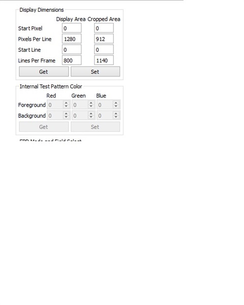
    I still have problem about third question. i already pick the Video Mode (like the picture)

    It seems like i can't set the "cropped area". After i set "start pixel" to 400, it will default back to 0.

    And actually i didn't understand what  these tabs mean. If i just want project the part of  912*1140  image (size like 200*200) ,how should i set?

    Thank you.

    Zichao Bian


  • Hello Zichao,

    Cropped Area - this is the actual source input resolution. For example - 912x1140, It remains constant. 

    Display Area - this is what you can select portion of the DMD and display the image, i.e., selecting a valid value which is less than 1280x800 would result in displaying in the entire image within user set area.

    For example - if the source is 912x1140 and user set's Display Area = 640x480, then the input 912x1140 resolution image is scaled down to 640x480 and then displayed from (0,0) position - top right corner on the DMD.

    Couple of very important things - 

    1. This is applicable only in VIDEO MODE.

    2. In the VIDEO MODE, if the Display Area is set to 1280x800 (WXGA resolution) then image is displayed full screen.  

    3. This is functionality should not be used in application where 1:1 pixel mapping needed like Machine Vision Structured Light or 3D Printing etc...

    Regards,
    Sanjeev

  • Thank you Sanjeev.

    I think i understand it now. 

    And there is another few things i want to know.

    (1)Can i light up only one pixel? or set only one mirror active at time?

    (2)And when i project a static image ,all mirrors will maintain they state or 'shake' all the time?

    (3)i try to project binary image but i figure out that 'black' seems not that black.

    (4)Can i change the offset setting?i want the center of the DMD is aligned exactily with the optical axis of the projection lens.

    (5)Do you know where can i find the cable fit for J14 and J11(name for this kind cable)?

    (6)I still want to use third part software to control the DLP4500(c,c++,python,matlab.etc). The method you mention before seems didn't work. I can't upload image to the DLP4500.


    Thank you

    Zichao

  • Hello Zichao,

    #1 and #2.

    Mirrors are continuously refreshed, in cyclic fashion, LOAD - RESET - LOAD - RESET... in the load step the the data under each mirror is updated, RESET is when the Mirror takes position based on the data loaded. Even if the same bit continues over multiple load operations the mirror continue to move when reset step applied, for example - bit value under the mirror is '1' all the time, so mirror disturbed for few us time then set to the position when a RESET step is applied.

    #3.

    This is the off-state light coming out of the DMD you may want to refer to basics about optical design http://www.ti.com/lit/an/dlpa022/dlpa022.pdf

    #4. 

    The light engine as such build with 100 offset, our design house offer customization to light engines you may want to contact to them. I think the light engine built will be very rigid so not sure, it allows moving the lens elements, better way to check with our design house.

    #5.

    You need to build one.

    You can find the male connector part details from the BOM. You can order female part and solder wires as required.

    #6.

    Which method? You mean this one?

    We can provide you inputs on how to go about, the DLPC350 is recognized as USB HID device,  with VID = 0451 and PID = 6401. I came across this website http://ahidlib.com/index.php/online-help/matlab-interface showing MATLAB interface to any generic HID device. You can try this and first.  Test if the DLPC350 HID device is detected. 

    The next step would be to  translate the .c code from GUI source into MATLAB code, the files you can look at are USB.c/USB.h and API.C/API.h. Now you write simple code to call APIs to control the device.

    Not sure what else we can help you with, you can use important files from the GUI source code, namely, hidapi-master folder, usb.c/.h, api.c/.h file and have a main function calling api.h interfaces. We have tried this method it should work. In short, you should be able to compile and build your c application easily.

    Regards,

    Sanjeev

  • Hello,

    Regarding the "issue" with 100% vertical offset (#4), we solved this by physically removing portion of the light engine plastic casing (also a part of the DMD heat sink as well) in order to move the projection optics in vertical direction. Additionally we cut a portion of the base plate away to give us space for mounting options for our own optics.

    If you do this you cannot attach the original projection optics with those 4 screws anymore. Also if you do decide to remove some of the casing, be aware that if you do get dirt between the DMD and the TIR prism, it is a tricky process to clean it and it you might cause some misalignment in the internal optics. 

    And I guess it's needless to say you don't have any warranty after that.

    Kind regards,

    Kari

  • Thank you!

    Zichao 

  • yeah, currently i try to use 100% offset to do my experiment , if it didn't work well ,i will have to try remove the light engine part.

    Thank you.

    Zichao Bian

  • Hi Sanjeev

    Sorry to bother you again.

    Right now i can run the 'AHidDemo2' file , i should change the VID and PID to 0451 and 6401 right?(otherwise the default parameter is 04D8 and 0123 ? )  and then i clicked connect button.(only "Found" in Status change to true)

    If what i mention before is correct, the problem i met is that when i select "Matlab Demo!" at the Messages tab, matlab will sent error notes like the below.

    Error using feval
    Undefined function 'lbMessages_Callback' for input arguments of type 'struct'.

    Error in gui_mainfcn (line 96)
    feval(varargin{:});

    Error in AHidDemo2 (line 43)
    gui_mainfcn(gui_State, varargin{:});

    Error in @(hObject,eventdata)AHidDemo2('lbMessages_Callback',hObject,eventdata,guidata(hObject))


    Error while evaluating uicontrol Callback

    I want to know do you ever face the same problem before?  (i already use mex and install compiler).

  • Hello Zichao,

    We want to let you know that, personally I haven't  used the matlab software for USB HID devices, this is something i could able to search on the web and found that it is can be useful, so i cannot comment on the problem you are mentioning for AHidDemo2 matlab code.

    Note, the for adaption you need to work in step wise, first, ensure USB device open / close are working with DLPC350 VID and PID to 0451 and 6401, this ensure the the physical path connection, now in the second step, you need to frame the messages (protocol part refer DLPC350 Programmer's Guide) and test the device send back response. 

    Regards,

    Sanjeev


  • Hello Zichao sir,

    I have one problem in operation of DLP LightCrafter 4500 EVM Device...
    everything process i have done completely. but when i click on SEND button in "Pattern Sequence" --> SEND --> "Validate Sequence" --> "PLAY"
    after clicking on play button the device does not show actual result it display only "default image".

    what kind of setting i want required for desired output.

    plz suggest me...

    u can mail me on email- dipak@softtact.com


    Thanks,
    Dipak