This thread has been locked.

If you have a related question, please click the "Ask a related question" button in the top right corner. The newly created question will be automatically linked to this question.

Contrast on Pico

Hi,

To start with here's the setup:

Pico -> Setup to run at 1440Hz (480wX320h, green led 33% PWM, all Non-linear functions turned off as specified in the Structured Light Applications document)

Feed src-> Windows box, sending a simple picture ( a black background with a red wire circle and a plus at its center)

I'd expect this to give me a bright circle and the plus sign and rest of the screen to be blank.

However the pico shows a very *noisy* background.

Is there some setting that I am missing here?

Warm Regards,

Abe


Src Image:

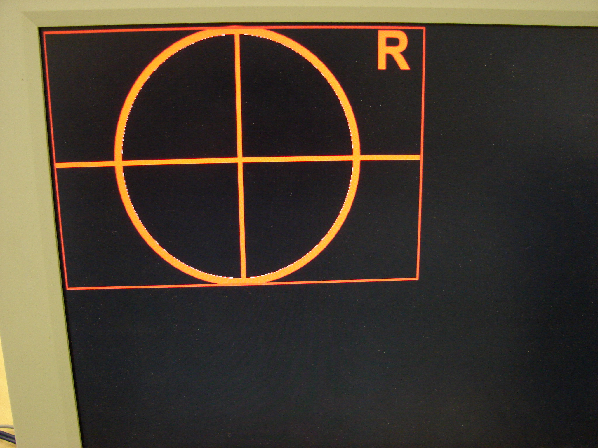
Resultant Image on Pico:

Video mode:

Click here to play this video


  • Hello Karnik.

    First - you may not be doing anything wrong. However, I must ask if you reassigned the green LED to red? Only one LED can be used in the 1440 Hz structured light mode. You mention that you are setting the green LED for 33% PWM (intensity). However, the pictures that you attached are showing the light to be red.

    Second - in the 1440 Hz structured light mode, each 16.67ms frame is divided into 24 separate monochrome fields which display sequentially the values of the 24 RGB bits which are on the HDMI input port during that 16.67 ms frame. This RGB value comes from the image being displayed by the PC, as captured by the HDMI port. Each pixel location in the image has a RGB888 value associated with it. The 1440 Hz 1-bit structured light mode displays a bright or dark pixel during each of the 24 sub-frames corresponding to the bit value in each bit position on the RGB port. Figure 5 in the application note "Using the DLP Pico 2.0 Kit for Structured Light Applications" illustrates this.

    If the input image sets only a few bits on the RGB port, then the resulting projected image may have illuminated pixels for only a few of the 24 subframes. This would make the image appear dim to the eye. However, the "correct' pixels are actually being illuminated at the correct time. But the resulting visual duty cycle is low - therefore dim or noisy in appearance. By way of understanding this, if the image from the PC is 100% white (RGB 255 255 255) in the image area, then the subframes will display a bright pixel for each of the 24 subframes.

    Perhaps this is why you are not seeing what you were expecting. I hope this helps. If you continue to have questions or problems, please let me know.

    Pascal

  • Thank you for your response Pascal.

    >First - you may not be doing anything wrong. However, I must ask if you reassigned the green LED to red? Only one LED can be used in the 1440 Hz structured light mode. >You mention that you are setting the green LED for 33% PWM (intensity). However, the pictures that you attached are showing the light to be red.

    To clarify, the application I am running can work in any of the three colors. I wrote up the question and then decided to take pictures to add to it. While taking the pictures, I thought why not try the red led mode and hence the red images.(yeah, that's a doh! on my part)

    >Second - in the 1440 Hz structured light mode, each 16.67ms frame is divided into 24 separate monochrome fields which display sequentially the values of the 24 RGB bits >which are on the HDMI input port during that 16.67 ms frame. This RGB value comes from the image being displayed by the PC, as captured by the HDMI port. Each pixel >location in the image has a RGB888 value associated with it. The 1440 Hz 1-bit structured light mode displays a bright or dark pixel during each of the 24 sub-frames >corresponding to the bit value in each bit position on the RGB port. Figure 5 in the application note "Using the DLP Pico 2.0 Kit for Structured Light Applications" illustrates >this.

    Which is exactly why I am using the 1440Hz mode. My application will be encoding a total of 24 frames of 1-bit size into 1 888 frame sent to the Pico. (24*60 = 1440 1-bit frames/second which is what I need)

    If the input image sets only a few bits on the RGB port, then the resulting projected image may have illuminated pixels for only a few of the 24 subframes. This would make the image appear dim to the eye. However, the "correct' pixels are actually being illuminated at the correct time. But the resulting visual duty cycle is low - therefore dim or noisy in appearance. By way of understanding this, if the image from the PC is 100% white (RGB 255 255 255) in the image area, then the subframes will display a bright pixel for each of the 24 subframes.

    I understand what you are trying to say here. But the src image has a black background which is essentially RGB 0,0,0. And the shapes are RGB 255,0,0 This is exactly what created the question in the first place. I'd expect nice crisp (relatively dim) shapes in front of a black background instead of the noise I see in the black regions of the image.

    If you want I can post the settings I am changing to set the display mode.

    Thanks.

    Warm Regards,

    Abe


  • Abe,

    Sorry my answer wasn't of much help. If you could send me your setup I can try to reproduce it here. Then, maybe I can see what is going on.

    Best regards,

    Pascal

  • Hi Pascal,


    Sorry for the delay in response. Here are the settings I am using. Contrast is still pretty bad.

    I also have an additional question. I hooked up an oscilloscope to Asyn0,1 & 3. The Asyn0 and 3 are adjustable as mentioned. However I found that Asyn1 doesn't pulse-out at 1440Hz. Instead it stays at 60Hz only. Is this expected? and is it possible to get it up to 1440Hz?

    (I basically require 3 sync strobes equally spaced apart within a single bit period (0.68ms @ 1440Hz => Asyn1 at a delay of 0ms, Asyn0 at a delay of 0.227ms and Asyn3 at a delay of 0.454ms)

    //Least significatn byte first
      Send to Reg: 0x04 (input source) > 0x00,0x00,0x00,0x00            //0. Select “Parallel RGB” input source: I2C sub-address x04, data x00000000
      Send to Reg: 0x05 (input resolution) >  0x07,0x00,0x00,0x00       //1. Set “Input Resolution” to “VGA Landscape”: I2C sub-address x05, data x00000007
      Send to Reg: 0x24 (external vsynch select) >  0x01,0x00,0x00,0x00 //2. Select external vertical sync source:• I2C sub-address x24, data x00000001
                                                                        //3. Reduce LED current to avoid potential LED degradation:
      Send to Reg: 0x0E (red led PWM Control) > 0x87,    0x02,0x00,0x00 // I2C sub-address x0E, data x00000287, red
      Send to Reg: 0x0F (grn led PWM Control) > 0x87,    0x02,0x00,0x00 // I2C sub-address x0F, data x00000287, green
      Send to Reg: 0x10 (blu led PWM Control) > 0x87,    0x02,0x00,0x00 // I2C sub-address x10, data x00000287, blue
                                                                        //4. Disable all non-linear pixel processing:
      Send to Reg: 0x82 (non-linear processing Automatic gain control enable) > 0x06,0x00,0x00,0x00 // Automatic gain control off – I2C x82, data x00000006
      Send to Reg: 0x92 (non-linear processing Color coordinate adjustment enable) > 0x00,0x00,0x00,0x00 // Color coordinate adjustment off – I2C x92, data x00000000
      Send to Reg: 0x26 (non-linear processing Video/graphics enhancement enable) > 0x00,0x00,0x00,0x00 // Video/graphics enhancement off – I2C x26, data x00000000
      Send to Reg: 0x62 (non-linear processing Non-linear processing inhibit) > 0x00,0x00,0x00,0x00 // Non-linear processing inhibit – I2C x62, data x00000000
      Send to Reg: 0x1f (display mode select to set to external patterns) > 0x06,0x00,0x00,0x00 //5. Select Display Mode: I2C sub-address x1F, data (x4-x9 for external patterns, see Table 3)
                                                                      // x6 1440 Hz, 1 bit green only R0%, G100%, B0% See Figure 5
      Send to Reg: 0xb2 (base clock for the camera strobe mux) > 0x02,    0x03,0x00,0x00 //6. Set base clock to rising edge, 3* 33.3ns = 100ns 
      Send to Reg: 0xc1 (delay for async0) > 0xff,0x00,0x00,0x00 //async0 is delayed by 2270 * 100 ns = 227us = 1/3 of 0.68ms
      Send to Reg: 0xbf (delay for async3) > 0xff,0x00,0x00,0x00 //async3 is delayed by 4540 * 100 ns = 454us = 2/3 of 0.68ms
      Send to Reg: 0xc2 (pulse width of strobe for async0) > 0xE8,    0x03,0x00,0x00 //async0 pulse width is 0.1ms = 100us = 100*10*100 ns = 1000 clocks  
      Send to Reg: 0xc0 (pulse width of strobe for async3) > 0xE8,    0x03,0x00,0x00 //async3 pulse width is 0.1ms = 100us = 100*10*100 ns = 1000 clocks


    Warm Regards,

    Abe

  • Abe,

    Thanks for posting your setup.  I will not be able to work on this until tomorrow (or perhaps the next day). I will get back to you within a couple of days to let you know how I am coming along.

    Best regards,

    Pascal

  • Abe,


    Pascal asked me to look into your setup to see if we could replicate the contrast issue you are experiencing.  I hope the following explanation helps you:


    I duplicated the setup you posted. I tried it with first the green, then the red LED enabled. I displayed an image with various regions of black (R=0, G=0, B=0), white (R=255, G=255, B=255), as well as regions with various RGB values.  I found that the Pico 2.0 kit worked as expected (as described in the Structured Light App Note) and displayed good contrast when the display values were black and white (as above). However, since in the 1440 Hz mode the 24 subframes display the RGB bits unweighted, it only takes a few non-0 bits in the RGB value to produce an apparently “noisy” or “grainy” image. Unless the black region of your image is actually RGB000, the Pico Kit will display it as a gray shade, even though the same region may look quite black on your computer display of the same image.  Again, this is because the 1-bit monochrome setting assigns all bits equal weight. This means that bits with little weight on your screen will affect the structured light mode projected image. For my test I gradually increased the brightness of my screen until it reached a setting where the monitor still looked black but the projected lines were grey.


    With regards to your other question, about the pulsing frequency of the Asyncs, only Asyncs 0 and 3 will match the frequency of your selected display mode.  In your setup description you didn’t include the commands to setup the output muxs (addresses x80, xB8, and xB7 as described on page 12 of the Structured Light Applications note), but I assume you did already since you can get Asyncs 0 and 3 to behave as intended.


    Regards,

    Raul