This thread has been locked.

If you have a related question, please click the "Ask a related question" button in the top right corner. The newly created question will be automatically linked to this question.

4710EVM : Programmatic Control Capability with Beaglebone Black / Linux

Other Parts Discussed in Thread: DLPC3439

Hi! Great product here!

I'm looking at trying to programmatically (via something like C++) control my 4710 EVM with a beaglebone black, ideally:

1) over USB (but optionally over i2c.)

2) using C++

The functions I need to perform are simple enough--I need to shutter/deshutter the projector (or simply the projected light, even), and I need to be able to set the current of each LED (usually to maximum).

If someone could point me in the right direction---ideally an SDK or straightup C++ code would be nice---I'd appreciate the help very much!

Thanks for reading!

-Luke

  • Hello Luke,

    Unfortunately we currently don't have sample code for the beaglebone black.

    You can connect your beaglebone black directly to the I2C lines of the DLPC3439 and send I2C commands.

    The software programmers guide is listing all of our supported I2C commands.

    www.ti.com/.../dlpu035.pdf

    Best regards,

    Nadine

  • Thanks Nadine!

    I'll try I2C, but also do you have any C++ code or an SDK for USB communication on a Linux-based computer at all? I could probably figure out how to make the BBB work, given that.

    Thanks again,
    -Luke
  • Hello Luke,

    I know that Beaglebone has a lot of code examples available online. You might want to check with the Beaglebone group if they have a code example or SDK already available for the use case you are looking for.

    Thanks,
    Nadine
  • Hi Nadine,

    my email is matt@collidertech.com, I am working with Luke on this project. Is there any way we can get the source code for the windows GUI application, "DLP LightCrafter Display v4.0 - 4710 EVM" ?

    We would like to make sure we are correct in the way we are communicating with the 4710 EVM. It does not seem to respond to commands that we send it, that should match what it is looking for, and seem to match what that GUI says it puts out. So we would like to make sure what we are actually writing on the i2c bus matches this application, which we know works properly.

    Thanks!
    Best Regards,
    Matt
  • Hello Nadine,

    actually even i am trying to make it work with Cypress API...

    I have Young Optics 4710 module with UV Led.. and i checked electronics its almost identical(They seperated it in 3 part pcb.. and in Gen2 we have 2 part pcb ).. but all basic communications are same AFAIK.... now they provide us few function in form of SDK 

    here is the code 

    public class Ddp343x
    {
    enum CommandType {
    WRITE,
    READ
    }

    enum CommandId {
    WRITE_LED_ENABLE = 0x52,
    READ_LED_ENABLE = 0x53,
    WRITE_LED_CURRENT = 0x54,
    READ_LED_CURRENT = 0x55,
    READ_TEMPERATRUE = 0xd6,
    WRITE_PROJCETOR_FLIP = 0x14,
    WRITE_PWR = 0xa0,
    READ_LIGHT = 0xac
    }

    CypressI2c mCpressI2c;
    public const byte cSlaveAddress7bit = 0x1B;
    const String cReadSlaveAddress = "37";
    const String cWriteSlaveAddress = "36";
    public const byte aSlaveAddress7bit = 0x39;
    const String aReadSlaveAddress = "73";
    const String aWriteSlaveAddress = "72";

    i think we just need to change few address like cSlaveAddress7bit etc....

    and yes cypress has linux source code too..

    i am just missing address AFAIK...i know they have custom firmware for MSP430.. 

    if they can do it with regular 4710 than we can surely do it (With Help of NADINE :))

    Thanks,

    Regards,

    himanshu

  • Hello Matt and Himanshu,

    We currently don't provide the source code for our GUI. We leave it up to our customers to create there own user interface if needed.

    Cypress provides an SDK which can be downloaded under following link:

    www.cypress.com/.../usb-serial-software-development-kit

    We also have an E2E post regarding how to start the communication to our DLP Controller via I2C.

    Please refer to following post:

    e2e.ti.com/.../452596


    The I2C commands are listed in our software programmers guide under following link:
    www.ti.com/.../dlpu035.pdf

    Thanks,

    Nadine
  • We don't care about the GUI. We care about the fact that TI's documentation is misleading. We understand how to talk on the i2c bus - we know that is what is happening. TI's chips are not responding to the commands TI's documentation says they should respond to.

    For instance, the documentation says that the slave address should be 36h. Should that not be written as just "36"? or with some other signifier that the quantity is being shown in the decimal value, rather than it's hexadecimal equivalent of 0x1b? If this primary item is written this way - it follows that ALL of the other commands are written out in this fashion (which I would consider wrong, but if it's consistent, then we can work with that). so that a command we want to use, say 52h, should really be written as 0x34. Can you confirm if that's correct? 

    We will have trouble verifying this, if we have to repeat this command 5 times (or more, or a random number of times) to get an actual result from the system.

  • Hello Matt,

    I am sorry that you are experiencing issues but I am trying to help to get this issue resolved.

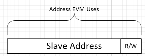
    TI defined the slave address as the actual slave address of the bus plus an extra bit to signify if we were doing a read (1) or a write (0) in the software programmers guide which would be 36h for a write command. The h is standing for hexadecimal and is common practice to clarify the numeric system.

    For the Cypress the slave address is actually just the slave address. Meaning without the last bit. So in reality the address is 0x1B for both read/write.

    I hope this will clarify the confusion.

    After setting GPIO5 High are you waiting  for GPIO6 to get High and then set GPIO9 high ?

    Thanks,

    Nadine

  • Hey Nadine--
    Thanks for your help. We were able to sort some of the issues out thanks to your tip about the GPIOs (which, incidentally, I didn't find in the documentation... just for those who may be interested in improving it :) )

    I now have another question if you're able to help answer it -- are there any special instructions for *reading* over I2C that I should be aware of? I'm not sure if the CyI2cRead(...) operation is enough. I seem to be getting mostly zeroes for the address locations that I'm interested in---namely 55h : read LED current---Even though our LED power when read by the GUI is 9501ma.

    Please help!

  • Hello Luke,

    For reading you would have to request the I2C bus in the same way as you have done it for a write command.
    The I2C address is still 0x1B as explained earlier in the thread.


    Cypress has sample code available under following link:

    http://www.cypress.com/documentation/software-and-drivers/usb-serial-software-development-kit

    Best regards,

    Nadine