This thread has been locked.

If you have a related question, please click the "Ask a related question" button in the top right corner. The newly created question will be automatically linked to this question.

DLP Lightcrafter 2000 EVM

Other Parts Discussed in Thread: DLPC2607, DLPDLCR2000EVM, TFP401, TFP401A

The manual says DLP2000NVM can be connected to raspberry pi too, Has anyone tried it out already. Or is this to come down the lane?

Thanks in advance

  • Hi there!

    Havent tried it yet, got mine a hour ago but cant seem to get it booting. only a solig green led on D3. Have you got your booting?
  • Just ordered mine, and I was wandering the exact same thing. Pretty keen on finding out..
  • Hi,

    I'm working on the same thing.

    I have the EVM wired up in 24 Bit mode. Pulling Pin 43 to ground switches the display from the normal "start screen" to another state. I guess now I would have to send the I2C commands as described in the User guide, but the Raspberry has no pins for I2C left. I'm not sure if you could wire the EVM in 18 bit mode to free up the I2C pins or if you loose all IO pins by switching the BCM into DPI mode. I'll test that in the next few days.

    The other option I'll try is to use an external I2C (USB) adapter or a small controller doing the housekeeping stuff.

    I'll keep you posted on my process.

    Christopher

  • Hi Kaushik,

    Yes, this EVM can be connected to anything that outputs 24-bit, 16-bit, or 8-bit RGB parallel video. We have not done it specifically for the Raspberry pi but I can think of a few ways to do this. The first approach would be to use the DPI of the raspberry pi, you can find information about it on this link :      

    This link shows you what GPIO pins can be configured for parallel RGB, 888 or 565 mode(24-bit or 16-bit).

    Next you should take a look at the user's guide for the DLPC2607 controller, as this is the controller used for the EVM. Link here:

    The user can control a lot of the projector's parameters through I2C commands, and at the bottom of page 16 you can read the command to change the video format. these can be sent just like the other I2C commands that were sent in page 6 of the DLPDLCR2000EVM User's guide.

    Again, I haven't done this on the Raspberry pi but from quickly reading the DPI link i posted above, the pi comes loaded with a file called "dpi24.dtb", This is a device tree overlay file for the kernel to configure the video specs and all the GPIO functionalities. I would expect this to work as it is by default, but let say it limits you from using certain GPIO or takes away your I2C lines, then make a copy of this file and edit it to what you need. after compiling this file and loading it, everything should work in theory. This is very similar to the same approach I did to make the EVM compatible with the Beagle Bone Black.

    There are other approaches such as buying separate hardware to convert whatever video format you want to output from the pi, to the 24-bit RGB of the EVM. Just remember you are dealing with a full Linux platform so there are a lot of ways to go about this. From looking at the Raspberry pi documentation, it seems that there is a lot of flexibility on controlling the GPIO, so you should be able to output video, have I2C, and other GPIO pins available with proper configuration.

    Once again, we have not done this with the Raspberry pi, but I provided you with the first two approaches that come to mind, and some useful links to get you started. I hope you find this helpful, and please keep us posted on any progress. We are eager to see what new applications for our EVM others can come up with.

    Regards,

    John Varela

  • Any luck? I am unable to get post this. 

    If not for this, is there a way we can add an interface to the EVM. say, a HDMI input

  • Thank you, John, very useful indeed. I have a few questions, though.

    1) Looking into the EVM pinout, its quite obvious which are the data lines, the vsync, hsync, pclk and dataen, and how these map directly to the RPi3 pins. As the physical connectors don't match, can you suggest any concrete way of connecting them - jumper wires, adapter (if offered anywhere), breadboard...

    2) The I2C pins on the EVM are also clear, but I am not quite sure if we can ever free up the I2C GPIOs, as long as we are using any DPI mode. Anyway, an external I2C component can work around this. But I am not sure what are the other pins used for - the VINTF (?), PROJ_ON_EXT (high when the EVM is ON?), HOST_PRESENTZ (?), GPIO_INIT_DONE (high when the EVM finishes initialization?), GPIO05 (?) and all the GRD (should we ground all of these to one or several of the GND pins on the RPi3).

    Regards,
    Stanimir
  • Stanimir,

    Let me answer these questions individually:

    1) For a small-scale DIY project, I would recommend a custom protoboard. Alternatively, you could also design an adapter board to interface the EVM with the Raspberry Pi. Ultimately, you could use this approach to interface the open GPIO pins with any host processor featuring enough pinouts.

    2) This is a good question. I will provide a brief description of some of the additional GPIO functions below:

    > VINTF is used as a reference voltage for communications (such as I2C) between the host processor and the EVM
    > PROJ_ON_EXT is an external control signal that, as you describe, can enable and disable the projection system digitally. The system will effectively turn off when this is driven low
    > HOST_PRESENTZ is an active-low signal which is used by the EVM to tell whether a host processor is connected to the system, and controls whether PROJ_ON_EXT is referenced by the system.
    > GPIO_INIT_DONE (or GPIO4) is high during initialization, and will go low after initialization is complete for the DLPC2607
    > GPIO5 is an extra GPIO pin that is used for motor control interface. By default, this is not needed unless such a motor is employed

    I also suggest reviewing the DLPDLCR2000EVM schematic, which can be found at www.ti.com/.../tidrs01.pdf, for more information about this design. I also recommend reviewing the DLPC2607 datasheet at www.ti.com/.../dlps030c.pdf for more information about the interface pinouts described above.

    Let me know if you have additional questions or concerns.

    Best Regards,
    Philippe Dollo
  • so i am trying to run the EVM using raspberry pi for the source data and using an arduino for the i2c and other pins.

    Do i now need to give VINTIF for i2c. If yes, what is the reference voltage here?
    Also if i just need to get the data from the raspberry pi and i am using the arduino for i2c what address of i2c am i supposed to give for auto initialisation. I am controlling the video resolution and output via raspberry pi.

  • Kaushik,

    The VINTF reference for I2C is 3.3V. It should be provided by the host processor (in this case the Arduino).

    Can you describe what you mean by auto-initialization? You may need to configure the DLPDLCR2000EVM to external video mode and set to the correct input resolution, but these things can be done independently of the Raspberry Pi.

    Let me know if I can elaborate further.

    Best Regards,

    Philippe Dollo
  • So the setup i currently have is that i am using raspberry pi for 6 pins (ext SDA, ext SCL, Vintif, Host presentz, proj on ext, gpio init done) and using the HDMI from raspberry to an adafruit TTL rgb converter that uses a Ti - TFP401/TFP401a. I have parallel rgb in place.

    I am unsure of what how the RGB pins are divided on the EVM and also the clock and resolution.

    AT this moment all i get is scattered colors on the evm. 

    Can the evm take any data input and resize it for the EVM or is that something that has to be configured on the Input. 

  • Kaushik,

    This is a great question. The important thing to note here is that the DLPC2607 data pins can actually be configured, so they may not be the same if you choose a different video specification (such as RGB565 vs RGB888). In addition, input resolution is not automatically detected on the DLPC2607. As such, you need to configure the EVM's input resolution to match what you are supplying.

    To send commands to reconfigure your system (during normal operation) consult the DLPC2607 programmer's guide (at http://www.ti.com/lit/ug/dlpu013/dlpu013.pdf). Sections 2.4.1.5 and 2.4.1.6 respectively contain information on the input data format and input resolution registers.

    To review the pin mapping for various input data formats, look at the DLPC2607 datasheet (at http://www.ti.com/lit/ds/dlps030c/dlps030c.pdf). Specifically, look at section 7.3.1 for figures with detailed pin mapping information.

    Let me know if where I can assist you further. I hope this helps.

    Best Regards,


    Philippe Dollo

  • Can anyone give me the values that are to go onto these fields in the image attached

    TIA

  • I have used a HDMI to parallel RGB converter. I have plugged the pins as given in dlps030c but as i see, there is no data being transmitted via pins 16-23 of the EVM. 

    Can someone clarify what is the pin structure we use. and i would like to understand how to use all the pins as i have a 24 pin converter.

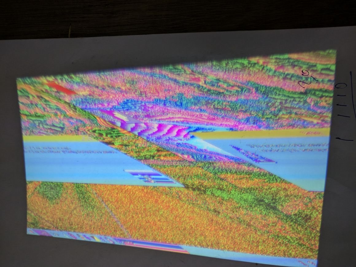
    So the image is slanty and also colors are not proper. I assume if we fix the pins, the colors should be proper. But the slant issue is something i was unable to fix

  • Can someone please help me with this? I am really stuck here. the colors are messed up.

    My setup is using an adafruit tfp401 that gives 24pins for RGB data and Hsync/Vsync/dataen/pclk

    i can see an image but the colors are messed. on checking, i realised that no matter what mode i use, pins 16-23 dont take any data.
  • Kaushik,

    Have you verified the color space configuration is correct on the DLPC2607? It supports multiple video formats (although it should be set to RGB888 by default). In addition I would also suggest verifying the resolution setting is correct on the DLPC2607. The DLPC2607 does not auto-detect the input resolution so you need to configure it so the image will show up correctly. The "slant" effect you are describing is a pretty common symptom of the resolution setting being wrong.

    The DLPC2607 programmer's guide (www.ti.com/lit/dlpu013) features information on the I2C commands associated with these settings. Let me know if examining these settings helps you any. In particular, I suggest looking at section 2.4.1.5 and 2.4.1.6 for the commands I am referring to.

    Best Regards,
    Philippe Dollo