This thread has been locked.

If you have a related question, please click the "Ask a related question" button in the top right corner. The newly created question will be automatically linked to this question.

Second Stage Loader for the 5502 - Question

Other Parts Discussed in Thread: TMS320VC5501

Hello,

I am working on a project that utilizes the TMS320VC-5502 and M25P80 serial flash. The hardware will be configured to use the "SPI EEPROM Boot Mode". I need to be able to load one of two images stored in flash. After browsing the forum and the TMS320VC5501/5502 Bootloader document, it seems like a second stage loader (this would be the third image in flash?) will allow me to accomplish loading one or the other image. I am looking for any TI references that might detail creating a second stage loader or possibly any examples of a second stage loader for the 5502. Since it seems the second stage loader will emulate the boot loader (except that the boot table of the two images in flash will not start at EEPROM address zero), any examples of a SPI EEPROM Boot Loader would be helpful.

Thanks for any information or comments on the planned approach.

Stephen

  • Stephen,

    Here is an example.  You just have to implement 'blockRead' to read from the SPI EEPROM, and 'pack16_msb' to pack characters into words, and you're all set.

    #include <stdint.h>

    // If valid, the boot image starts with this word.
    #define BOOT_IMAGE_MAGIC 0x09AA

    err_t boot(void) {

        err_t result;
        uint16_t buffer[512];
        uint32_t flashByteAddr = 0;
        
        // Read header bytes:
        blockRead(flashByteAddr, (char*) buffer, 8);
        
        // Pack:
        pack16_msb(buffer, 8);
        
        // Verify that first word is our happy value:
        if (buffer[0] != BOOT_IMAGE_MAGIC) {
            result = ERR_STORAGE;
        } else {
            uint32_t entryPoint;
            
            // Copy the entry point for later use:
            entryPoint = ((uint32_t) buffer[1] << 16) + (uint32_t) buffer[2];
            
            // Skip any register configuration data.
            flashByteAddr = 8 + buffer[3];
            
            // Loop until program is loaded:
            for (;;) {
                // Load each block into memory.
                // Read header bytes:
                blockRead(flashByteAddr, (char*)buffer, 6);
        
                // Pack:
                pack16_msb(buffer, 6);
                
                if (buffer[0] == 0) {
                    // A block size of zero marks the end of the program.
                    // Branch to the entry point:
                    ((void (*) (void)) entryPoint)();
                } else {
                    uint16_t blockRemaining, padWords;
                    uint32_t destAddr;
                    uint16_t *pDest; 
                    
                    blockRemaining = buffer[0];
                    destAddr = ((uint32_t) buffer[1] << 16) + (uint32_t) buffer[2];
                    pDest = (uint16_t*) destAddr;
                    flashByteAddr += 6; // increment address by header size
                    // Compute padding words P is such that:
                    //  M = S + 2 + P is a multiple of 4.
                    padWords = 4 - (blockRemaining + 2 & 3) & 3;
                    
                    while (blockRemaining) {
                        uint16_t wordsToRead = MIN(
                                blockRemaining,
                                _countof(buffer) / 2  // half the size, as unpacked
                        );
                        const uint16_t *pSrc = buffer;
                        
                        blockRead(flashByteAddr, (char*)buffer, wordsToRead * 2);
                        pack16_msb(buffer, wordsToRead * 2);
                        
                        blockRemaining -= wordsToRead;
                        flashByteAddr += wordsToRead * 2;     // byte address!
                        
                        // Copy words to destination.  We could use memcpy, but if
                        //  it happens to not be an intrinsic we would have another
                        //  code dependency to worry about being overwritten...
                        for ( ; wordsToRead; --wordsToRead) {
                            *pDest++ = *pSrc++;
                        }
                    }
                    
                    // Add padding to get to next header location:
                    flashByteAddr += padWords * 2;
                }
            }
        }
    
        return result;

    }

  • Hi Bill,

         Thanks for the example code, I really appreciate it.  It should do the trick!

    Stephen

  • Hi Bill,

           Just as I received your reply back in May, I was pulled onto another more pressing project.  I am now back on trying to complete a second stage boot application for the 5502. The example code defines a value "Boot_Image_Magic" as 0x09AA.  Then checks the image for this value in the first word of the image.  Could you please let me know what  format is the image in? I can't seem to find this value in the images I create with the HEX55 tool. 

    Thanks,

    Stephen

  • Stephen,

    Be sure to create your images with the -b and -boot options.

    Regards,

    Bill

  • Hi Bill,

         Still having problems.  My image still does not seem to have the format referenced in the sample program you provided.  Below is the HEX55 command line that I use to create the binary:

    *************

    @ECHO OFF
    set /p inputfile= Enter input file name:
    set /p outputfile= Enter output file name:
    set /p fileformat= Enter File Format Option:


    REM *** Now build the bin file

    hex55 -boot -v5510:2 -serial8 -exclude vectors -%fileformat% -o %outputfile% - %inputfile%
    PAUSE>nul

    ***************

    I use "b" as the File Format Option.

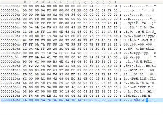
    This results in the below binary file:

    I must be missing a step somewhere to get the type of file format the sample program is looking for.

    Any help would be appreciated.

    Thanks,

    Stephen

  • Stephen,

    I'm sorry, I led you on a bit of a goose chase.  My example code was for a C5515 bootloader, which has a slightly different file format from the C5510 family.  The C5505/5515 boot loaders expect that magic word; the 5510 and its derivatives do not.  You can remove that check from the code, and make sure it starts copying bytes right from the first byte.

    Another difference I see is that the C5515 bootloader uses 16-bit section byte counts; the C5510 uses 32-bit byte counts.  So that will be another tweak to my example.  Otherwise the table formats are the same.

    Again my apologies for giving imprecise information.

    Regards,

    Bill

  • Hi Bill,

         Thanks! I have made some progress thanks to the new information.  I will keep you posted and let you know if successful or not.

    Thanks again,

    Stephen 

  • Hi Bill,

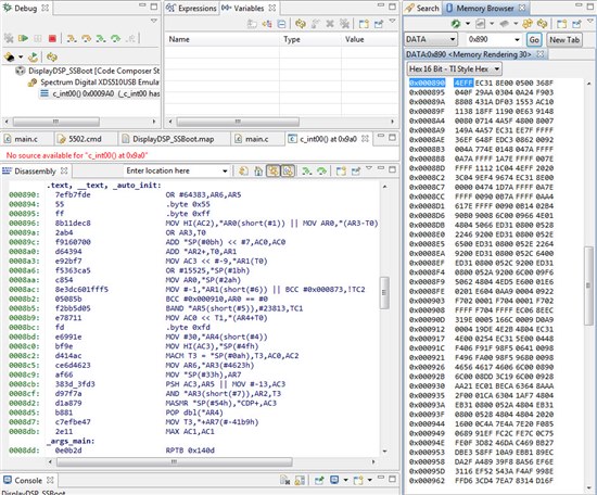
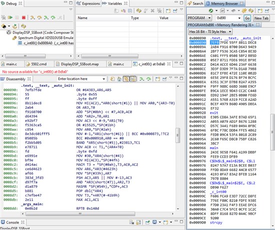
         Thanks for all the help to date.  I think I am close, but still cannot get the program working.  I seem to be writing the data from flash to internal RAM incorrectly.  I have simplified the example program you sent me and it is included in the this post along with some screen captures from my debugging sessions. In essence, I copy a byte from the serial flash and shift it into a 16 word, then copy the next byte and add it to the 16 bit word, then write the word to internal RAM. When I single step through the code, the date is being written to the correct address in internal RAM, so I am thinking that I am not packing the data correctly.

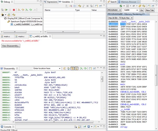
         The first screen capture is when the test application has been loaded by the CCS debugger. The test application runs okay when loaded by the debugger.

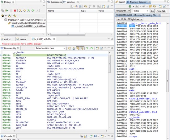
    The next screen capture is the test application loaded by my second stage boot application.  As you can see, the program memory is different from the first image, where the test application is loaded by the debugger.

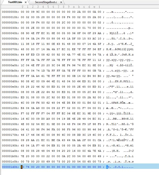
    Next image is the test application binary file:

    Here is the SSBoot source file:

    6170.main.c
    //==============================================================================
    // Filename: main.c
    // Purpose:  Implementation of main functionality of the Display DSP Second Stage
    //           Boot.
    // Author:   Stephen P. Davis
    //
    // -----------------------------------------------------------------------------
    //       COPYRIGHT 2014 ROCKWELL COLLINS.  All rights reserved
    // -----------------------------------------------------------------------------
    // The technical data in this document (or file) is controlled for export under
    // the Export Administration Regulations (EAR), 15 CFR Parts 730-774.
    // Violations of these laws may be subject to fines and penalties under the
    // Export Administration Act.
    //
    //==============================================================================
    //
    /*............................. FILE INCLUSION .............................*/
    
    
    #include <stdint.h>
    #include <stdbool.h>
    #include <string.h>
    #include <file.h>
    #include <stdio.h>
    #include "c5502.h"
    #include "spiflash.h"
    /*............................. Defines ...........................*/
    
    #define firstSectionByteCount  0x8
    
    /*............................. Main ...........................*/
    
    void main(void)
    {
        int result = 1;
        int spd = 1;
        unsigned long int flash_offset = 0;
    
        uint16_t buffer[512];
        unsigned int buffer_index = 0;
        uint16_t destWord;
        uint16_t destAddr;
        uint16_t *pDest;
        uint16_t blockRemaining;
    
        // Initialize SPI
        spiflash_init();
    
        // This is prototype code!! Get the first 512 bytes of the executable in flash.
        // Will only get first 512 bytes. This is adequate for Test001.bin.
    
        flash_offset = 0x30000;
        buffer_index = 0;
        while (buffer_index < 512)
        {
        	buffer[buffer_index++] = spiflash_read_byte(flash_offset++);
        }
    
        // The buffer now contains the boot block and the code for the test program.
        // Save the start address which is bytes 2 and 3
    
        uint16_t entryPoint = (buffer[2] << 8) + buffer[3];
    
        // Set the buffer index to point to the first 32-bit Section Byte Count
    
        buffer_index = firstSectionByteCount;
    
        // Process each section until program is loaded
    
        for(;;)
        {
            // Get the Section Byte Count (sbc)
        	uint32_t sbc = 0;
        	sbc = buffer[buffer_index++] << 24;
        	sbc = sbc + buffer[buffer_index++] << 16;
        	sbc = sbc + buffer[buffer_index++] << 8;
        	sbc = sbc + buffer[buffer_index++];
        	if (sbc == 0)
        	{
        		// A block size of zero marks the end of the program.
        		// Branch to the entry point:
    
        		((void (*) (void)) entryPoint)();
        	}
        	else
        	{
    
        		blockRemaining = (uint16_t) sbc;
        		// Get the Section Byte Start Address (sbsa)
        		uint32_t sbsa = 0;
        		sbsa = buffer[buffer_index++] << 24;
        		sbsa = sbsa + buffer[buffer_index++] << 16;
        		sbsa = sbsa + buffer[buffer_index++] << 8;
        		sbsa = sbsa + buffer[buffer_index++];
        		destAddr = (uint16_t) sbsa;
        		pDest = (uint16_t*) destAddr;
    
        		//*** DEBUG ***
        		while(spd)
        		{
        			result++;
        			result++;
        			result--;
        			result--;
        		}
        		//*** ENDDEBUG ***
    
        		while(blockRemaining)
        		{
        	    	destWord = (buffer[buffer_index++] << 8);
        	    	destWord =destWord + buffer[buffer_index++];
        			*pDest = destWord;
        			//Adjust counters and pointers and lions, oh my!
        			blockRemaining = blockRemaining -2;
        			*pDest++;
        		}
        	}
        }
    }
    

    Thanks,

    Stephen 

  • Hi Bill,

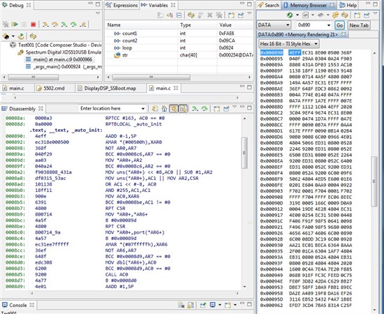
          Some additional screen captures. The screen capture below was taken right after the Test program was loaded by the second stage loader.  It is a view of "Data" memory and matches with the data in the .bin file.  So, I think that according to "Data" view of memory, I copied then data from the .bin file correctly and to the correct location in memory. However, if you look at the disassembly window, the instructions are not correct.

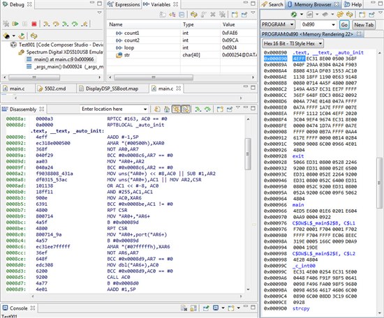
    Below is the same session, viewing the "program" memory.  It does not match the "data" memory view.

         When I load the same test program with the debugger, the "program" memory view and the "data" memory view match:

    Thanks,

    Stephen

  • Stephen,

    I'm glad you posted this second update.  I was confused, because in your first post, the screen-shot for the 'program as loaded by the debugger' did not match the binary file data.  In your second post it does.

    I'll take a look at your source file to see what is going on.

    Regards,

    Bill

  • Stephen,

    I think I got it; another difference between the bootloaders.  The destination addresses in the .bin file are byte addresses.  The DSP uses word addresses for data.  So just change line 96 in your program from:

    pDest = (uint16_t*) destAddr;

    to 

    pDest = (uint16_t*) (destAddr >> 1);

    and you'll be all set.  (I'd add a comment too.)

    Regards,

    Bill

  • Hi Bill,

         Thanks.  Your suggestion was right on.  As soon as I made your suggested change, everything started to work. Thanks for hanging in there with this problem.  Your help is really appreciated.

    Question Answered and Problem Solved!!!

    Regards,

    Stephen