


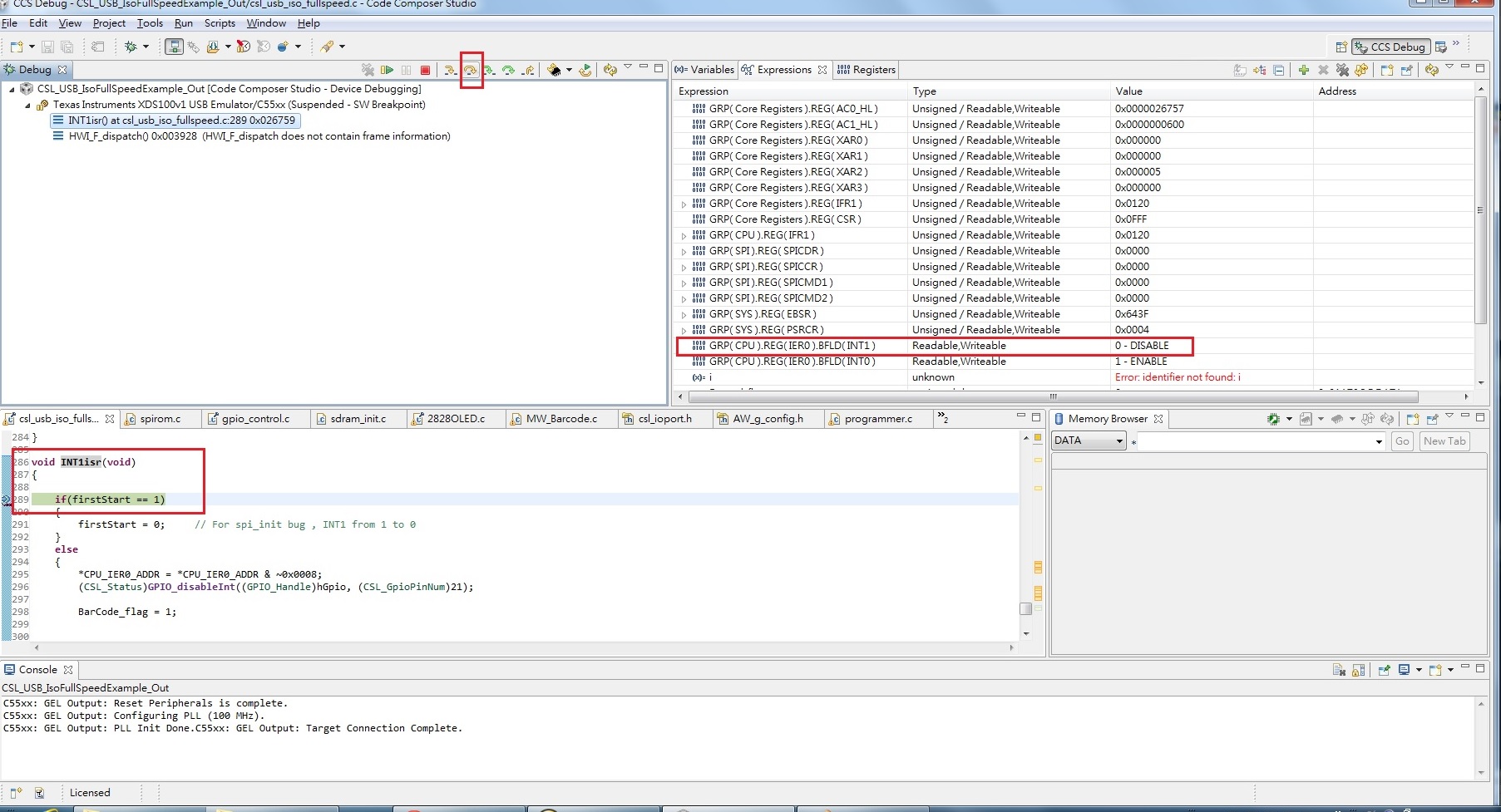
If I use SPI init , then the program will affect INT1 status.
In other words , the code flow is not correctly.
Could you give me any solution?
============================================
Enable spirom_init() flow :
main() -> CSL_acTest() -> INT1isr-> Mytask();
Disable spirom_init() flow :
main() -> CSL_acTest() -> Mytask();
============================================
// CPU C5515
// Board : customer
---------------------------------------------------
// code:
---------------------------------------------------
void main(void)
{
CSL_Status status;
Uint32 gpioIoDir;
Uint16 val;//, first_flag;
//I2C_to_uart_init();
/* Clock gate all peripherals */
CSL_SYSCTRL_REGS->PCGCR1 = 0x77FD; // bit11:EMIF , bit1:SPI
CSL_SYSCTRL_REGS->PCGCR2 = 0x007F;
/* Configure EBSR */
#if defined(USE_I2S0_PB) || defined(USE_I2S0_REC)
/* SP0 Mode 1 (I2S0 and GP[5:4]) */
CSL_FINST(CSL_SYSCTRL_REGS->EBSR, , MODE1);
#else
/* SP0 Mode 2 (GP[5:0]) -- GPIO02/GPIO04 for debug */
CSL_FINST(CSL_SYSCTRL_REGS->EBSR, SYS_EBSR_SP0MODE, MODE0); //MODE0
#endif
#if defined(USE_I2S1_PB) || defined(USE_I2S1_REC)
/* SP1 Mode 1 (I2S1 and GP[11:10]) */
CSL_FINST(CSL_SYSCTRL_REGS->EBSR, SYS_EBSR_SP1MODE, MODE1);
#else
/* SP1 Mode 2 (GP[11:6]) */
CSL_FINST(CSL_SYSCTRL_REGS->EBSR, SYS_EBSR_SP1MODE, MODE2); /* need GPIO10 for AIC3204 reset */ //MODE0
#endif
/* PP Mode 1 (SPI, GPIO[17:12], UART, and I2S2) */
CSL_FINST(CSL_SYSCTRL_REGS->EBSR, SYS_EBSR_PPMODE, MODE5); //MODE5
/* Reset C5515 -- ungates all peripherals */
C5515_reset();
//EMIF & SPI FLASH
CSL_FINST(CSL_SYSCTRL_REGS->EBSR, SYS_EBSR_SP1MODE, MODE0);
spirom_init();
CSL_SYSCTRL_REGS->PCGCR1 |= 0x02;
CSL_FINST(CSL_SYSCTRL_REGS->EBSR, SYS_EBSR_SP1MODE, MODE1);
/* Initialize DSP PLL */
status = pll_sample();
if (status != CSL_SOK)
{
#ifdef DEBUG_LOG_PRINT
LOG_printf(&trace, "ERROR: Unable to initialize PLL");
#endif
exit(EXIT_FAILURE);
}
/* Clear pending timer interrupts */
CSL_SYSCTRL_REGS->TIAFR = 0x7;
/* Initialize GPIO module */
#if !defined(USE_I2S0_PB) && !defined(USE_I2S0_REC)
/* GPIO02 and GPIO04 for debug */
/* GPIO10 for AIC3204 reset */
gpioIoDir = (((Uint32)CSL_GPIO_DIR_OUTPUT)<<CSL_GPIO_PIN2) |
(((Uint32)CSL_GPIO_DIR_OUTPUT)<<CSL_GPIO_PIN4) |
(((Uint32)CSL_GPIO_DIR_OUTPUT)<<CSL_GPIO_PIN10) |
(((Uint32)CSL_GPIO_DIR_OUTPUT)<<CSL_GPIO_PIN11) |
(((Uint32)CSL_GPIO_DIR_OUTPUT)<<CSL_GPIO_PIN12) |
(((Uint32)CSL_GPIO_DIR_OUTPUT)<<CSL_GPIO_PIN13) |
(((Uint32)CSL_GPIO_DIR_OUTPUT)<<CSL_GPIO_PIN14) |
(((Uint32)CSL_GPIO_DIR_OUTPUT)<<CSL_GPIO_PIN15) |
(((Uint32)CSL_GPIO_DIR_OUTPUT)<<CSL_GPIO_PIN16);
#else
/* GPIO10 for AIC3204 reset */
gpioIoDir = (((Uint32)CSL_GPIO_DIR_OUTPUT)<<CSL_GPIO_PIN10);
#endif
status = gpioInit(gpioIoDir, 0x20600340, 0x00600340);
if (status != GPIOCTRL_SOK)
{
#ifdef DEBUG_LOG_PRINT
LOG_printf(&trace, "ERROR: Unable to initialize GPIO");
#endif
//exit(EXIT_FAILURE);
}
val = *(ioport volatile unsigned *)0x1c00; //EBSR
val |= 0x003F;
*(ioport volatile unsigned *)0x1c00 = val; //Set A15-A20 MODE
val = *(ioport volatile unsigned *)0x1c17; //PDINHIBR1
val |= 0x0800;
*(ioport volatile unsigned *)0x1c17 = val; //Pull-down GPIO11
val = *(ioport volatile unsigned *)0x1c0A;
val &= ~0x0800;
*(ioport volatile unsigned *)0x1c0A = val; //Set GPIO11 = 0
val = *(ioport volatile unsigned *)0x1c0A;
val |= 0x0800;
*(ioport volatile unsigned *)0x1c0A = val; //Set GPIO11 = 1
}
void CSL_acTest(void)
{
#if 1 // 2014
LongWait0(5);
// clear all interrupts (IFR0 and IFR1)
*CPU_IER0_ADDR = *CPU_IER0_ADDR | 0x000C;
LongWait0(5);
#endif // 2014
}
void INT1isr(void)
{
if(firstStart == 1)
{
firstStart = 0; // For spi_init bug , INT1 from 1 to 0
}
else
{
*CPU_IER0_ADDR = *CPU_IER0_ADDR & ~0x0008;
(CSL_Status)GPIO_disableInt((GPIO_Handle)hGpio, (CSL_GpioPinNum)21);
Code_flag = 1;
*CPU_IFR0_ADDR = *CPU_IFR0_ADDR | 0x0008;
GPIO_enableInt((GPIO_Handle)hGpio, (CSL_GpioPinNum)21);
}
}
void spirom_init( )
{
Int16 i;
/* Reset Counter value */
SYS_PRCNTR = 0x04;
/* Reset SPI Module */
SYS_PRCNTRLR = 0x00ff;
for(i=0;i<100;i++) {;}
/* Enable SPICLK,RX,TX & CS0 */
//SYS_EXBUSSEL =(0x5<<12); // mode5 , Table 3-6. LCD Controller, SPI, UART, I2S2, I2S3, and GP[31:27, 20:18] Pin Multiplexing
SYS_EXBUSSEL =(0x6<<12); // mode6
//SPI init
SPI_SPICC2 = (0<<15); // Reset SPI
SPI_SPICC1 = 0x0031; // 2MHz input clock
SPI_SPIDC1 = 0x0000;
SPI_SPICR2 &= ~0x30F8; // Enable CS0
SPI_SPICR2 |= 0x0038; // Set word length as 1-byte
SPI_SPICC2 = (1<<15); // Enable SPI
while((SPI_SPISR1 & 0x0001) != 0) {}; // Wait for SPI ready
spirom_status_set( 0xc3 ); // Clear Block Protection
//return;
}
Uint16 spirom_status_set( Uint8 val)
{
/* Issue read status command */
statusbuf[0] = spirom_CMD_WRSR;
statusbuf[1] = val;
spirom_cycle(statusbuf, 2);
return statusbuf[3];
}
void spirom_cycle(Uint16 *buf, Uint16 len)
{
Uint16 i;
SPI_SPICR1 = 0x0000 | len - 1;
i = SPI_SPIDR2; // Dummy read
/* Spirom access cycle */
for (i = 0; i < len; i++)
{
SPI_SPIDR2 = buf[i] << 8;
SPI_SPIDR1 = 0x0000;
SPI_SPICR2 = 0x0039; // 8-bit words, read
while((SPI_SPISR1 & 0x0002) == 0) {};
buf[i] = SPI_SPIDR2 & 0xff;
}
/* Wait for transfer to complete */
while((SPI_SPISR1 & 0x0001) != 0) {};
// EVM5515_waitusec(100);
}
