This thread has been locked.

If you have a related question, please click the "Ask a related question" button in the top right corner. The newly created question will be automatically linked to this question.

DMA sync events are MIA

I'm still struggling to get a McBSP DMA chain going with my C5510.  The McBSP is working great when I manually read it with MCBSP_read32( hMcbsp );  When I try to trigger DMA transactions off of the RSYNC events from this McBSP port, everything goes awry.  :(  Here's the situation...

  • McBSP0 hooked up to a serial ADC.  
  • FSR is the conversion clock for the ADC.
  • The DR and CLKR pins are also hooked up to the ADC, and again, I can read the ADC just fine using MCBSP_read32()
  • The McBSP is generating FSR, and CLKR using the Sample Rate Generator, and they're outputs.
  • I've set up DMA transactions to source from the McBSP like so...


adc->dmaCfg.dmacssal = (DMA_AdrPtr)((Uint16)(MCBSP_ADDRH(adc->serial.hMcbsp, DRR1) << 1));

adc->dmaCfg.dmacssau = (Uint16) 0x0000;

  • I've setup the destination address like so...


adc->dmaCfg.dmacdsal = (DMA_AdrPtr) (((Uint32)(demod->ring_start)<<1)&0xFFFF);

adc->dmaCfg.dmacdsau = (((Uint32) demod->ring_start) >> 15) & 0xFFFF;

  • I've plugged my ISR into the dispatcher.


// Save off the event id.  

adc->uiDmaEvtId = DMA_getEventId( adc->hDmaRx );


// Save off our callback function pointer

adc->fCb = callback;


// Map the event for DSP BIOS.

IRQ_map( adc->uiDmaEvtId );


adc->attrs.arg = (Arg)adc;

adc->attrs.ier0mask = 1;

adc->attrs.ier1mask = 1;


// Plug the ISR into the dispatcher along with its argument

HWI_dispatchPlug( adc->uiDmaEvtId, (Fxn)ADC_DMA_isr, &adc->attrs );


The DMAs never happen, and at first I thought it was because I had setup the ISR incorrectly, or hadn't appropriately enabled the IRQ or something.  But then I started polling the SYNC bit of DMACSR, and it never goes high.  

But here's where the plot thickens.  If I do a manual read (MCBSP_read32), I get a SYNC event in my DMA engine.  And I can do manual reads like that and watch the DMA counts increment as well.  WHAT GIVES???  

I've been wondering if maybe the fact that I'm sourcing the FSR and CLKR has anything to do with it.  I have the McBSP in free running mode, so those lines are always going.  (Verified with an LA.)  Or I was wondering if DRR1 is still the appropriate address for the DMA since it's a 32-bit read, and DRR2 must be read first for data integrity issues.  I don't know.  I'm grasping at straws here.  Anyone have any in-depth insight into the McBSP/DMA interactions in the C55xx series?  Any help would be much appreciated.  Thanks.


p.s. I do call DMA_start... see below

adc->state = ADC_DMA_RUNNING;

        IRQ_globalDisable();

        IRQ_clear( adc->uiDmaEvtId );

        // Enable the interrupt associated with DMA0/ADC0

        C55_enableInt( adc->uiDmaEvtId );

        DMA_start( adc->hDmaRx );

        IRQ_globalEnable();

        // Start the port

        MCBSP_start( adc->serial.hMcbsp, MCBSP_RCV_START | MCBSP_SRGR_START | MCBSP_SRGR_FRAMESYNC, 33 ); 


  • FF,

    What versions of CCS, BIOS and Code Gen are you using?  Can you provide register dump of McBSP and DMA channel you are using?  You never mention how you setup the McBSP.  Is it configured to generate the sync event to the DMA?

    Regards.

  • OK.  Here comes the big DUMP of info.  :)  

    CCSv4.1.2.00027

    BIOS : 5.41.02.14

    Code Gen Tools : TI v4.3.5

    I'm using the c55 CSL RMK macros to setup the McBSP and the DMA registers.  Here's the McBSP setup.

       adc->serial.sConfig.spcr1 = \

            MCBSP_SPCR1_RMK( MCBSP_SPCR1_DLB_OFF,               // Digital Loop Back off

                                MCBSP_SPCR1_RJUST_RSE,          // Sign extend and Right Justify

                                MCBSP_SPCR1_CLKSTP_DISABLE,     // No clockstop

                                MCBSP_SPCR1_DXENA_OFF,          // DX delay off

                                MCBSP_SPCR1_ABIS_DISABLE,       // Set to 0

                                MCBSP_SPCR1_RINTM_RRDY,         // Interrupt on RRDY

                                MCBSP_SPCR1_RSYNCERR_NO,        // No Frame Sync Errors

                                MCBSP_SPCR1_RRST_DISABLE );     // Don't enable it yet


        adc->serial.sConfig.spcr2 = \

            MCBSP_SPCR2_RMK(    MCBSP_SPCR2_FREE_YES,           // Free run on breakpoint

                                MCBSP_SPCR2_SOFT_NO,            // Doesn't matter

                                MCBSP_SPCR2_FRST_RESET,         // Frame Sync comes from generator

                                MCBSP_SPCR2_GRST_RESET,         // Bit Clock comes from generator

                                MCBSP_SPCR2_XINTM_XRDY,         // Doesn't matter

                                MCBSP_SPCR2_XSYNCERR_NO,        // Doesn't matter

                                MCBSP_SPCR2_XRST_DISABLE );     // No transmitter


        adc->serial.sConfig.rcr1 = \

           MCBSP_RCR1_RMK( MCBSP_RCR1_RFRLEN1_OF(0),

                           MCBSP_RCR1_RWDLEN1_32BIT);           // 32-bit data            


        adc->serial.sConfig.rcr2 = \

            MCBSP_RCR2_RMK( MCBSP_RCR2_RPHASE_SINGLE,           // Single phase

                            MCBSP_RCR2_RFRLEN2_OF(0),           // Doesn't matter

                            MCBSP_RCR2_RWDLEN2_32BIT,           // Doesn't Matter

                            MCBSP_RCR2_RCOMPAND_MSB,            // No companding

                            MCBSP_RCR2_RFIG_NO,                 // Bad Frame Sync ignored

                            MCBSP_RCR2_RDATDLY_1BIT );          // 1 bit of data delay.

    adc->serial.sConfig.srgr1 = \

                MCBSP_SRGR1_RMK( MCBSP_SRGR1_FWID_OF(0),            // 1 bit wide Frame Sync (value of 0)

                                 MCBSP_SRGR1_CLKGDV_OF(47) );       // GLKGDV of 5 is our intented rate


            adc->serial.sConfig.srgr2 = \

                MCBSP_SRGR2_RMK( MCBSP_SRGR2_GSYNC_FREE,            // Run free; no sync to CLKs

                                 MCBSP_SRGR2_CLKSP_RISING,          // Doesn't matter

                                 MCBSP_SRGR2_CLKSM_INTERNAL,        // DOES MATTER.  We generate the CLKs internally

                                 MCBSP_SRGR2_FSGM_FSG,              // Doesn't matter

                                 MCBSP_SRGR2_FPER_OF(33) );         // DOES MATTER : 34-1 = 33 clocks per Frame Sync


            adc->serial.sConfig.pcr = \

                MCBSP_PCR_RMK(  MCBSP_PCR_IDLEEN_RESET,

                                MCBSP_PCR_XIOEN_SP,                  // Special purpose TX

                                MCBSP_PCR_RIOEN_SP,                  // Special purpose RX

                                MCBSP_PCR_FSXM_INTERNAL,             // Internal Frame Sync Generation TX

                                MCBSP_PCR_FSRM_INTERNAL,             // Internal Frame Sync Generation RX

                                MCBSP_PCR_CLKXM_OUTPUT,              // Bit Clock is an output TX

                                MCBSP_PCR_CLKRM_OUTPUT,              // Bit Clock is an output RX

                                MCBSP_PCR_SCLKME_NO,                 // Internal Clock is the source of the clock

                                MCBSP_PCR_DXSTAT_1,                  // Doesn't matter.  Only used for GPIO.

                                MCBSP_PCR_FSXP_ACTIVELOW,            // TX active low frame sync

                                MCBSP_PCR_FSRP_ACTIVEHIGH,           // RX active high frame sync

                                MCBSP_PCR_CLKXP_RISING,              // TX on rising edge

                                MCBSP_PCR_CLKRP_FALLING );           // RX on falling edge


    // Open our McBSP port.

        adc->serial.hMcbsp = MCBSP_open( adc->nWhichADC, MCBSP_OPEN_RESET );


        // Make sure we got a valid port

        if( INV == adc->serial.hMcbsp ){

            adc->serial.hMcbsp = 0;

            return -ENO_MCBSP;

        }


        // Save off the McBSP event ID number

        adc->serial.intnum = MCBSP_getRcvEventId( adc->serial.hMcbsp );


        // Configure our port

        MCBSP_config( adc->serial.hMcbsp, &adc->serial.sConfig );

  • And here's the DMA setup.


    // Set our DMA channel 1,0 depending on which is correct.

        adc->uiDmaChanRx = adc->nWhichADC;    


        // Open the DMA channel and save off the handle.

        adc->hDmaRx = DMA_open( adc->uiDmaChanRx, DMA_OPEN_RESET );


        // Check for valid.

        if( INV == adc->hDmaRx ){

            adc->hDmaRx = 0;

            return -ENO_DMA;

        }


        // Setup the CSDP register

        //      This is the source and destination register, and controls

        //      which memory banks are accessed by the DMA engine, as well

        //      as the data widths involved and bursting.

        adc->dmaCfg.dmacsdp = \

            DMA_DMACSDP_RMK( DMA_DMACSDP_DSTBEN_NOBURST,     // No bursting to destination

                             DMA_DMACSDP_DSTPACK_OFF,        // Packing is irrelevant in 32-bit.

                             DMA_DMACSDP_DST_SARAM,          // Destination is in SARAM.

                             DMA_DMACSDP_SRCBEN_NOBURST,     // No bursting from source

                             DMA_DMACSDP_SRCPACK_OFF,        // No packing from source

                             DMA_DMACSDP_SRC_PERIPH,         // Source is a perispheral

                             DMA_DMACSDP_DATATYPE_32BIT );   // Data is inherently 32-bit.


        // Set up the CCR register

        //      The CCR register controls how the addressing occurs on both

        //      the source and destination addresses.  It also controls the

        //      autoinitialization behavior, or auto-repeat.  

        adc->dmaCfg.dmaccr = \

            DMA_DMACCR_RMK( DMA_DMACCR_DSTAMODE_POSTINC,      // Increment the dest addr after each write

                            DMA_DMACCR_SRCAMODE_CONST,        // Source addr is constant

                            DMA_DMACCR_ENDPROG_OFF,           // This is right

                            DMA_DMACCR_REPEAT_ALWAYS,         // This is right

                            DMA_DMACCR_AUTOINIT_ON,           // Autoninit on.

                            DMA_DMACCR_EN_START,              // DMA channel enable

                            DMA_DMACCR_PRIO_HI,               // Reading our samples is the highest prio

                            DMA_DMACCR_FS_ELEMENT,            // Sync is an element transfer

                            4*adc->nWhichADC + 1 );           // Sync on McBSP0,1 Receive Events

                            // WHAT IS DMA_DMACCR_SYNC_REVTA0 vs DMA_DMACCR_SYNC_REVT0


        // Set up the CICR register

        //      Configure control of what interrupts are generated.  We're 

        //      interested in frame interrupts.  We also want to know if there

        //      is ever a dropped sample, so we've turned on drop IE as well.                                  

        adc->dmaCfg.dmacicr = \

            DMA_DMACICR_RMK( DMA_DMACICR_BLOCKIE_OFF,         // We shouldn't need block interrupts

                             DMA_DMACICR_LASTIE_OFF,          // No last frame interrupts

                             DMA_DMACICR_FRAMEIE_ON,          // Frame interrupts on

                             DMA_DMACICR_FIRSTHALFIE_OFF,     // No half-frame interrupts

                             DMA_DMACICR_DROPIE_ON,           // Interrupts for dropped events

                             DMA_DMACICR_TIMEOUTIE_OFF );     // Timeout interrupts off.


        // This is how our autoinit should rock.  We should DMA in a full

        // TDMA frame with each DMA "block".  A DMA "frame" will consist of

        // 625 samples, or 2 bursts.  4 DMA "frames" make up one DMA "block".

        // So the autoreload will DMA full TDMA frames into the ring buffer.   

        adc->dmaCfg.dmacen = DMA_DMACEN_RMK(625);   // 625 elements in each frame 

        adc->dmaCfg.dmacfn = DMA_DMACFN_RMK(4);     // 4 frames in each block.  A block would consist of a full TDMA frame


        // Destination is our ring buffer in SARAM

        adc->dmaCfg.dmacdsal = (DMA_AdrPtr) (((Uint32)(demod->ring_start)<<1)&0xFFFF);

        adc->dmaCfg.dmacdsau = (((Uint32) demod->ring_start) >> 15) & 0xFFFF;


        // Source is the McBSP0.

        //adc->dmaCfg.dmacssal = (DMA_AdrPtr)0x2800;

        adc->dmaCfg.dmacssal = (DMA_AdrPtr)((Uint16)(MCBSP_ADDRH(adc->serial.hMcbsp, DRR2) << 1));

        adc->dmaCfg.dmacssau = (Uint16) 0x0000;


        // Now that all of the registers are setup, we'll configure the DMA

        // and actually write them all in.  At this point, we'll have a fully

        // ready to run DMA engine that should be ready to accept a "start" 

        // call and just go.

        DMA_config( adc->hDmaRx, &adc->dmaCfg );


    // Save off the event id.  

        adc->uiDmaEvtId = DMA_getEventId( adc->hDmaRx );


        // Save off our callback function pointer

        adc->fCb = callback;


        // Map the event for DSP BIOS.

        IRQ_map( adc->uiDmaEvtId );


        adc->attrs.arg = (Arg)adc;

        adc->attrs.ier0mask = 1;

        adc->attrs.ier1mask = 1;


        // Plug the ISR into the dispatcher along with its argument

        HWI_dispatchPlug( adc->uiDmaEvtId, (Fxn)ADC_DMA_isr, &adc->attrs );


        // Set our ADC to be idle.

        adc->state = ADC_DMA_IDLE;


  • I was trying to generate SYNC events from the McBSP to the DMA engine on RRDY.  I assumed that happened when I set the McBSP SPCR1 RRDY interrupts generation, and then set the DMA to SRC off of my McBSP DRR1.  Is there an additional step I'm not aware of?  If so, I'd love to know where that's documented.

    Also, I still wonder about whether I should give DRR1 or DRR2 as the source address to my DMA engine, given that it's a 32-bit read, and all of the McBSP documentation says to read DRR2 first in 32-bit applications.  I couldn't tell if that's true for DMA read access as well.   

    I'll try to get a register dump of my DMA regs and post them in a follow up.

  • So I've been trying to find the actual memory addresses for the DMA and McBSP control registers.  In the datasheet for the 5510, I see 0x0E00 for DMAGCR for example, but that's not an actual memory address.  You have to use some "port" keyword to make a pointer to that and read it.  Is there actually a CCS view that shows the control registers?

  • There are actually 3 different "memory" spaces with the C5000 DSPs.  The peripheral registers are in I/O space.  If you open a memory window you should be able to choose between DATA, PROGRAM and I/O.  Choose I/O, then your address 0x0E00 will show the DMAGCR register content.

    Regards.

  • Ha!  Thanks, you're right.

    DMA setup for DMA_CHAN0

    (DMAGCR, GSCR, GTCR)

    0x000E00 : 0x08 ---- ---- ----

    (DMASCDP0 through DMACDFI0 )

    0x000C00 - 0x000C0F : 0x0E 0x41 0x0A 0x40 0x00 0x00 0x08 0x04 0x71 0x04 0x00 0x00 0x02 0x00 0x00 0x00


    And for completeness, the McBSP setup  (McBSP0)

    (DRR20 through XCERH0)

    0x00280 - 0x00281E : 0x01 0xFF 0x00 0x00 0xC0 0x07 0xA5 0xA0 0x00 0x00 0x21 0x2F 0x00 0x00 0x00

    0x00 0x00 0x00 0x28 0x00 0x00 0x00 0x00 0x00 0x00 0x00 0x00 0x00 0x00 0x00 0x00

  • FF,

    You said you polled on SYNC for DMA.  Have you tried watching RRDY to make sure that the serial port has new data?  I'm not sure what goes on when you read the DRRs manually.  I think watching RRDY is a better test because that is what generates the REVT.

    Regards.

  • I actually tried both.  I started a while(1) loop where I just checked SYNC and RRDY every time through the loop using the get field macros, and breakpointed if true.  It was never true.  RRDY never went high and neither did SYNC.

    However, if I manually did a McBSP_read32(), I would see SYNC go high afterward.  (But that's not a legitimate fix.)

    It seems like my McBSP isn't generating the SYNC events without a manual read.  

    I don't know if this helps, but I have Chip ID : 0x9ea45607:28226648 and Chip Rev : 25874 (decimal).

    It's a DSK5510 board from Spectrum Digital and they say it's a Rev2_2 device.  I define CHIP_5510PG2_2 in my preprocessor.  I wondered if registers might have moved around in silicon revs or something... but I think I have the right chip etc etc.  Not 100% sure, but I think it's right.

  • FF,

    The fact that you never see RRDY high is an indication that the McBSP hasn't received any data.  As far as I know RRDY should always indicate the availability of data in the DRRs.  This is confusing at the moment.  Since the McBSP is the master, it should clock in something from the ADC even if it were rubbish.  I need to look at your McBSP settings again. 

    Where did you get the Chip ID: and Chip Rev:  I've got an SD DSK also, I can compare.  I think you have the latest device rev though with Rev 2.2

    Another question you asked about the DRR read order.  I saw in a couple of places in the McBSP UG that for word length > 16 you need to read DRR2 first to prevent it from accidentally being overwritten.

    Regards.

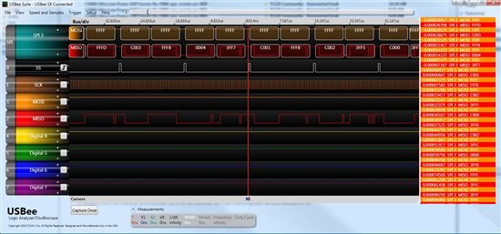
  • EXACTLY!!!  :)  I agree 100%!  Since my chip is the master, and it's ALWAYS pumping out the bit clock and frame clock, there should always be data in DRR and RRDY should always be high, in my estimation.  I have a little USBee logic analyzer pod, and as soon as I MCBSP_start(), I see Frame Sync and the Bit Clock buzzing away and the ADC is putting out valid data on the DR0 line.  But even if the ADC were putting out garbo, I'd think it would still assert RRDY.  


    That scope shot is taken literally while I'm waiting for DMA's and SYNC and my isr to be called, with no joy.


    I got chip ID and such from the CSL Library routines like so :

    #include <chip.h>

    ...

    ...


    printf( "Chip ID 0x%8lx:%8lx\tChip Rev : %d\n", 

            CHIP_getDieId_High32(), 

            CHIP_getDieId_Low32(), 

            CHIP_getRevId() 

            );


    So when I set DMA source addr, should I set DRR2, or DRR1?  i.e.

    adc->dmaCfg.dmacssal = (DMA_AdrPtr)((Uint16)(MCBSP_ADDRH(adc->serial.hMcbsp, DRR2) << 1));

    or

    adc->dmaCfg.dmacssal = (DMA_AdrPtr)((Uint16)(MCBSP_ADDRH(adc->serial.hMcbsp, DRR1) << 1));


    When I do a McBSP_read32(), the CSL function does the right thing, but I don't know how the DMA reads it.  That was my question regarding DRR1 vs DRR2.


  • Look at McBSP UG, sec 2.1.2 for explanation on why to read DRR2 first.  Still looking at the other stuff.

    Regards.

  • FF,

    I was looking at your register dump and I think you have configured the I/O memory window to display 8 bit data instead of 16 bit.  The numbers you reported don't make sense to me otherwise.  Can you confirm?  If so, could you post registers as 16 bit data?

    Regards.

  • FF,

    I went back and looked at my DSK5510 package from Spectrum Digital and see that they have a sample app that passes data from Line-In to Line-Out.  It is part of the Board Support Library and is located here on my system: <CCS3.1 Folder>\examples\dsk5510\bsl\dsk_app.  This app uses McBSP and DMA to manage the data.  Have you tried this on your system?  If it works, then we should have something to compare against your configuration.  Want to make sure that there are no HW issues.

    Regards.

  • 16-bit TI style Hex for the McBSP regs :  0x002800 -> 0x00281E

    0004 3FF5 0000 0000 02C0 2007 00A5 00A0 0000 0000 3021 002F 0000 0000 0000 0000

    0000 0000 0F28 0000 0000 0000 0000 0000 0000 0000 0000 0000 0000 0000 0000


    16-bit TI style Hex for the DMA Channel 0 Regs : 0x000C00 -> 0x000C0F

    000E 43C1 000A 0040 5002 0000 2308 0004 0271 0004 0000 0000 5004 2308 0000 0000


    Regarding their demo apps, I've not been able to get them to build in CCSv4.1.  I don't have CCSv3.x installed on my machine.  My old box had it, but when I got a new Vista 64 box, I never went back and reinstalled it.  So I have the dsk5510 install dirs inside of CCSv4.1.  Upon build, I get lots of errors that look BIOS-related.  "Cannot find biosi.a55l".  Undefined Symbol "DARAM".  Undefined Symbol "HWI_INT11".  etc etc.  There's no .tcf file in these examples, and CCSv4 complained a lot when it imported the legacy project about how there would be issues and to check a message.log.  Incidentally, biosi.155l isn't in my filesystem anywhere.  It's also looking for clki.a55l, which is also not there.  I'll keep looking into it though.  Maybe I can find a way to get it to build.

  • We have a 5510 project with audio codec samples transferred in and out via the McBSP and DMA in auto-init mode.  The code was written by a software vendor in assembly and he initially could not get this to work.

    He finally found that by starting the McBSP just before the DMA it mysteriously sprang into life.  I thought this worth mentioning as your setup sounds similar and I note you are starting the DMA first and it is easy to try.......

    Regards, Andrew

  • FF,

    I've got CCS3.1 still installed.  Let me see if the SW works on that, then can tell if it's worth trying to port to CCSv4.

    Register values look better.  I can comparte if the SD app works.

    Regards.

  • Hey Andrew, Thanks for chiming in!  

    So I went to try Andrew's suggestion, and switched back to my app after the struggles getting the dsk_app to run.  Now I get all kinds of crazy BIOS errors on build that I didn't get a couple of hours ago.  My "myapcfg.h" file that is autogenerated by the tools is gone.  I get the following from the TConf editor if I try to open the .tcf

    "js: "C:/ccsv4_1/xdctools_3_16_02_32/include/utils.tci", line 947: Error: Can't load platform definition 'ti.platforms.dsk5510': Error: Can't find configuration seed: ti/bios/config/cdb/c55xx.cdb

    Correct any script errors in C:/SVN/myapp/code_composer/.gconf/myapp/myapp.tcf

    using the Configuration Tool or a text editor, if necessary.


    TConf initialization arguments:

    -e environment['config.importPath']='C:/SVN/Myapp/code_composer;C:/ccsv4_1/bios_5_41_02_14/packages' -e environment['config.scriptName']='myapp2.tcf'"


    I went to the C:\ccsv4_1\bios_5_41_02_14\packages\ti\bios\config\cdb dir and there was no longer a c55xx.cdb in there.  So I copied the appropriate file from the C:\ccsv4_1\bios_5_41_02_14\packages\ti\bios\config\update\4.90.280 folder.  Now my myappcfg.h gets generated again, but I get the following errors on build in Code Composer.


    Severity and Description Path Resource Location Creation Time Id

    [ ***** USER ERROR ***** - ] STS_Obj parameter error. myapp line 0 1274884166817 34925

    [ ***** USER ERROR ***** - ] STS_Obj was passed too few parameters. myapp line 0 1274884166817 34924

    [E0300] The following symbols are undefined: myapp line 0 1274884166817 34926

    [E9999] Bad term in expression myapp line 0 1274884166815 34921

    [E9999] Invalid mnemonic specified myapp line 0 1274884166814 34918

    [E9999] No matching right parenthesis myapp line 0 1274884166815 34922

    [E9999] Operand missing myapp line 0 1274884166814 34919

    [E9999] Substitution symbol operand expected myapp line 0 1274884166815 34923

    [E9999] Syntax Error myapp line 0 1274884166814 34917

    [E9999] Unexpected trailing operand(s) myapp line 0 1274884166814 34920


    It seems like Code Composer completely lost its mind when I tried to import that dsk_app.  :(  I honestly don't know enough about the build tools to know what to do next with this.  :/  Any ideas?

  • FF,

    Wow, I'm sorry about suggesting the SD app now.  BTW, it does work fine on CCS3.1. 

    I think the problem you are having is that you took the .cdb file from an older version of BIOS.  Version 4.90 is what came with CCS3.1.  Not sure what happened to the orignial C55xx.cdb file.  To get you (hopefully) back to your original state I am attaching the .cdb from my 5.41 folder for you to try.  It's a zip file because I think there are restrictions on the types of files we can upload.  Let me know if this works.

    Regards.

    c55xx.zip
  • LOL.  Comedy of errors today.  :)  I copied it in, and get the same errors as I did with the other cdb.  This newer cdb is 315 kB, whereas the old one was over 600 kB.  Also, the following warnings were there before and continue now.

    Severity and Description Path Resource Location Creation Time Id

    [E0300] Cannot define an absolute symbol with a floating-point value; symbol's value will be encoded in floating-point format myapp/Debug myappcfg.h55 line 138 1274887510569 34941

    Which corresponds to this line of code in myappcfg.h55

    CLK_MICROSECONDS    .set 1000.000000


    [E0300] Cannot define an absolute symbol with a floating-point value; symbol's value will be encoded in floating-point format myapp/Debug myappcfg.h55 line 205 1274887510569 34942

    And that's from this line in myappcfg.h55

    PWRM_PWRM_INITVOLTS .set 1.600000

  • FF,

    Man I can't believe this.  You should be back to where you started from.  I talked to a colleague who knows CCSv4 better than I do and we can't come up with an explanation of what is going on.  The values that the compiler is complaining about are defined in BIOS and I can see the same values if I open another C5510 BIOS project and look at the .tcf file.

    To recover she suggested that you make a new workspace and try to import your project into the new workspace.  If that doesn't work, then you should try recreating the project, but use all your old source files.  This should eliminate any corrupt definition/configuration files that occurred in your workspace/project.

    In the mean time we are going to try and import the CCS3.1 project like you did and see what happens.  If it happens to us also, then we will report as a bug to be investigated.  Your BIOS install should not be corrupted by the import no matter whether you have problems with the imported project or not. 

    Let me know if this works for you.

    Regards.

  • Cool.  I'll work on it from my end.  Thanks for cranking away on this.  I do have all of this under source control in our SVN repository, so I can revert my local project and just lose any of my recent changes.  But that wouldn't revert any workspace-type issues, or any bios build tree issues.  But I'll try both, in order.  

  • For some Good News :

    Changing to "Release" from Debug and then back to Debug has fixed the Bios build problems.  I'm now JTAG'ing and debugging.

    I turned on my McBSP before starting the DMA engine this time, as Andrew suggested.  The first time I ran it, I got an interrupt in my frame completion DMA isr!  (whoo hoo!  First time that's happened!)  However, I didn't get anymore, so I'm going to look into whether I need to clear that interrupt differently.  

    For the bad news :

    In subsequent runs, the isr never got called again.  :(  (sad face)


    But I'll call that progress.

  • Hmmm, so we are making progress.  I got lots of DMA isrs to happen this time.  :)  So that's good.  But it's not consistent.  It seems like the trick that got it working was adding the following into my TSK that responds to the DMAs...


    tempdata = MCBSP_read32( adc->serial.hMcbsp );

            temp = DMA_FGETH( adc->hDmaRx, DMACSR, SYNC ) << 1;

            temp |= DMA_FGETH( adc->hDmaRx, DMACSR, DROP );

            element_count = DMA_RGETH( adc->hDmaRx, DMACEI );

            frame_count = DMA_RGETH( adc->hDmaRx, DMACFI );

            TSK_yield(); 


    Almost like I'm "priming the pump" or something with some manual McBSP reads.


    In further experiments, just having that code in there isn't sufficient.  I have to set a break point at TSK_yield(), and "play" to that breakpoint 4 or 5 times TILL I start to see SYNC go high.  Then if I remove the breakpoint, the DMAs going flying.  


    OK, and here's the entire scenario where they work.


    1.) Start debug of a session

    2.) Step through my main routine setting up my DMAs and McBSPs

    3.) Run out of main and jump into my TSK.  In TSK land, I start the DMA engine.

    4.) In a while loop in that TSK (below) I breakpoint on TSK_yield.

    void FXN_F_read_samples(  ) {

    // Wait for a go signal to start reading SEM_pend( &SEM_start_reading, SYS_FOREVER ); // Set the callback function the ISR should call adc->adc_dma_set_callback( adc, samples_ready ); // Start the reading from our ADC. adc->adc_dma_start( adc );

    while( 1 ){

    tempdata = MCBSP_read32( adc->serial.hMcbsp );

                 temp = DMA_FGETH( adc->hDmaRx, DMACSR, SYNC ) << 1;

                 temp |= DMA_FGETH( adc->hDmaRx, DMACSR, DROP );

                 element_count = DMA_RGETH( adc->hDmaRx, DMACEI );

                 frame_count = DMA_RGETH( adc->hDmaRx, DMACFI );

                 TSK_yield();            

            }

    }

    5.) The first time out of board reset that I run the app, SYNC only goes high once.  (After the second breakpoint.)  After that it's always low, and I never get any DMAs.

    6.) If I "restart" the application (Target->restart) and repeat the same sequence of events, "SYNC" is high every time I step that loop. 

    7.) I remove the breakpoint and hit "run" and the DMAs and ISRs all hit like they should, and my little LEDs go crazy blinking all of this.

    8.) All of my processing takes place, (Currently just sign extending the data... everything else is commented out.)

    9.) Go get a soda.


    If I reset the board, however, or "end" the debug session by clicking the stop button, then we go back to the beginning with the need for a "restart".


    My ISR does the following, and I *think* it's correct.


    void ADC_DMA_isr( void *param ){


        adc_dma_t *adc = (adc_dma_t *) param;


        /* clear interrupt flag                                       */

        DMA_RGETH( adc->hDmaRx, DMACSR );


        if( adc->fCb != (void*)0x00000000 )

           adc->fCb( (void *)adc );


        return;

    }


    That function pointer calls the following function


    void samples_ready( void *param ) {

        // Pointer to our param.

        adc_dma_t *adc = (adc_dma_t *)param;


        // Save out which buffer this came from before we lose it

        nBuff = adc->nWhichBuffer;


        SEM_post( &SEM_samples_ready );


        DSK5510_LED_toggle( adc->nWhichBuffer & 0x1 );


    }


    That unblocks a processing task to do whatever on the samples.  So great!  I can DMA!  Any thoughts on the "having to restart the app to make it work" issue???

    I'm still thrilled to have gotten a SYNC event and a DMA though!  Whoo hoo.  soda.consumption++;


  • Some added info.  It looks like my manual reads within that while loop are generating the SYNCs that are causing the DMAs to happen.  I changed things up a little bit to demonstrate it.


    void FXN_F_read_samples(  ) {

        Uint16 temp = 0;

        Uint16 element_count;

        Uint16 frame_count;

        Uint32 tempdata;

        volatile int n = 0;


    // Wait for a go signal to start reading

            SEM_pend( &SEM_start_reading, SYS_FOREVER );


            // Set the callback function the ISR should call

            adc->adc_dma_set_callback( adc, samples_ready );


            // Start the reading from our ADC.

            adc->adc_dma_start( adc );


            while( 1 ){

    while( !n ){ tempdata = MCBSP_read32( adc->serial.hMcbsp ); temp = DMA_FGETH( adc->hDmaRx, DMACSR, SYNC ) << 1; temp |= DMA_FGETH( adc->hDmaRx, DMACSR, DROP ); element_count = DMA_RGETH( adc->hDmaRx, DMACEI ); frame_count = DMA_RGETH( adc->hDmaRx, DMACFI ); } TSK_yield(); } }


    So at startup, I let the app run as is with the McBSP_read32() doing work.  I see DMAs.  My ISR gets called, etc etc.

    After a few seconds of running, I pause it, and change the volatile int n to 1, and guarantee that the MCBSP_read32() never occurs.

    No more DMAs.  No more blinky LEDs.  (Sad Face)


  • FF,

    Update.  We tried to import SD app to CCSv4 and found it wouldn't work because the app is built with BIOS 4.90.  This is an old version of BIOS which doesn't support the TCF configuration files (among other things).  However, it didn't break our CCSv4 install like yours.  The .cdb seed file never when away.  Not sure what happened with your setup. 

    So if you wanted to migrate the SD app to CCSv4 the best way would be to convert the dsk_app1.cdb to a .tcf file using the utility cdb2tcf.exe which came with CCS3.3 and BIOS 5.x.  Doesn't seem to be in CCSv4.  If you are interested you can get BIOS version 5.3x from this web site:  http://software-dl.ti.com/dsps/dsps_registered_sw/sdo_sb/targetcontent/bios/index.html.  Install the package to get the utility, but it's recommended to use at least BIOS 5.41 in CCSv4 due to enhancements/bug fixes.  Once the .cdb is converted we think the best way to port the SD app to CCSv4 is to create a new project and add all the source files.

    Something fishy with the DMA/McBSP operation.  If you watch RRDY in McBSP does it ever get set without your "priming the pump"?  I haven't looked much at the SD app yet, but it runs indefinitely for me.  I captured the register settings and want to look at config differences.  You may want to look at how they set up the peripherals to see if anything looks much different from what you are doing.

    Regards.

  • TommyG, 

    So I modified code a little bit to check that final scenario of RRDY being high.  My TSK now looks like this...

    while( 1 ){

    while( !n ){ temp = MCBSP_rrdy( adc->serial.hMcbsp ) << 2; temp |= DMA_FGETH( adc->hDmaRx, DMACSR, SYNC ) << 1; temp |= DMA_FGETH( adc->hDmaRx, DMACSR, DROP ); if( temp & 0x4 ) temp = 0; } TSK_yield();

    }

    I put in the if( temp & 0x4 ) so I had somewhere to put a breakpoint and check its value.  RRDY is always 1, but SYNC is always 0, as is DROP.  The only time SYNC goes high is if I put the McBSP_read32() back in.   After it had been running some time, I changed n to 1 to cause the while loop to end, and ran it, but my DMAs/ISRs never tripped.

    It seems like the only time SYNC goes high is when I manually read the port.  i.e. The reading of DRR1,2 makes SYNC go high.  But that implies a kind of chicken and egg problem.  :(

    I'm looking at the SD code for DSK_app1.  It's a little hard to tell exactly what they're doing because they're calling custom library routines to setup their McBSPs.  Namely...

    // Start the codec

        hCodec = DSK5510_AIC23_openCodec(0, &config);

    I notice they don't do much to setup their DMAs.  In fact, I was surprised to see that they don't touch most of the DMA registers.  Basically just the Frame sizing DMACEI,CFI,CFN regs.  I never see them call DMA_open, or DMA_config.  So I'm assuming that must be buried in the DSK5510_AIC23_openCodec() function.  

    D'oh.  Just found it in dsk_app1cfg_c.c.  I see that they're configuring for REVT2 in DMACCR.  They have a slightly different model with the double indexing.  They're using the older DMA csl without DMACSDP register.    Looks like they're setting the source address to 0x6002, which I'm assuming is the same as...

    adc->dmaCfg.dmacssal = (DMA_AdrPtr)((Uint16)(MCBSP_ADDRH(adc->serial.hMcbsp, DRR1) << 1)); 

    but for McBSP2.  (I'm using McBSP0).  I didn't see anything different functionally in the DMA setup though.

    For the McBSP, they're not setting RSYNC_ERR.  They're also not using the Sample Rate Generator at all.  (I am.)  Confirmed with their PCR settings.  Their CLK and FS signals are inputs.  I've wondered for a long time whether my CLK and FS being outputs and generating them internally has had anything to do with my DMA troubles.  :(

  • SUCCESS!  WHoo hoo!

    I needed to change two things to get this all to work.

    1.) Right before I called DMA_start(), I had to read DMACSR to clear it and enable any new events.  BUT, I had to read it into a volatile int, so that the read wouldn't get optimized away.  Also, in my ISR, I changed that DMACSR to volatile int i = DMA_RGETH( dma, DMACSR); as well.  I don't believe the ISR read was related, but it may have been.

    That change, however, wasn't completely sufficient to make it all work.  

    2.) I had to do one dummy read of the McBSP port to get things rolling.  So now my TSK looks like this...

    void FXN_F_read_samples(  ) {

         int i = 0;

         volatile Uint32 tempdata;

    // Wait for a go signal to start reading

    SEM_pend( &SEM_start_reading, SYS_FOREVER ); // Set the callback function the ISR should call adc->adc_dma_set_callback( adc, samples_ready ); // Start the reading from our ADC. adc->adc_dma_start( adc );

    // THIS HAD TO HAPPEN OR NO SYNCs come in tempdata = MCBSP_read32( adc->serial.hMcbsp ); while( 1 ){

    TSK_yield(); } }


    I hadn't been reading DMACSR before I called DMA_start();  I was only reading it in my isr to clear the interrupt.  I noticed SD was doing this in the DSK_app so I gave it a try.  I noticed that "SYNC" was set after that in my TSK and that DMAs were happening.  I commented out the manual McBSP reads, and everything stopped.  So I put one dummy read in and boom, it all worked.  No software intervention or continual dummy reads needed.  :D :D :D  

  • So one thing I'm also noticing is that it looks like I do indeed need to use DRR2 as my DMA source address like so


    // Source is the McBSP DRR2.

         adc->dmaCfg.dmacssal = (DMA_AdrPtr)((Uint16)(MCBSP_ADDRH(adc->serial.hMcbsp, DRR2) << 1));

         adc->dmaCfg.dmacssau = (Uint16) 0x0000;


    Otherwise, I get 16-bit data in my 32-bit sample.  FYI for anyone out there trying to do that.  

  • FF,

    Great news!  Hopefully all your work will help others with the McBSP / DMA combo in the future.

    Regards.

  • FF,

    One question if you have timeto clarify something for me.  Originally, I thought you said that RRDY was never 1 when you looked at it.  Now, it is always 1.  What changed?

    Regards.

  • I'm not sure.  I have a theory though.  If I do the following...


    McBSP_read32()

    temp = [check RRDY]


    Maybe RRDY won't be high immediately after a read.  But maybe it will.  I'm not sure why the change.  


    It's sooooo happy now though.  :)

  • Thanks for all of the details, and especially the summary of what worked.

    I had already gotten this to work with a 16-bit ADS chip under CSL, but without BIOS.

    When I first read the problem, I wondered whether you would be able to get 32-bit data, but it seems that you figured out which address to specify for that to work. Since I may need 32-bit serial data next time around, it helps to read that tip here.

  • Hey, I'm glad it helped.  :)


    If you need to read 32-bit data in a DMA transaction from a McBSP, here is the source address you'll need.


        // Source is the McBSP DRR2.

        adc->dmaCfg.dmacssal = (DMA_AdrPtr)((Uint16)(MCBSP_ADDRH(adc->serial.hMcbsp, DRR2) << 1));

        adc->dmaCfg.dmacssau = (Uint16) 0x0000;


    Where adc->serial.hMcbsp is a CSL McBSP handle returned from MCBSP_open();  

    I just wanted to make sure that ended up clear for everyone.  Reading from DRR1 did not work for 32-bit data, but reading from DRR2 does.