This thread has been locked.

If you have a related question, please click the "Ask a related question" button in the top right corner. The newly created question will be automatically linked to this question.

Minimum clocks for C5515 EMIF RSETUP and RHOLD

Other Parts Discussed in Thread: TMS320C5515

Hello,

I am interfacing to a high-speed A2D with the C5515.  The A2D has a parallel bus so I am using the EMIF to interface to it.  The EMIF data sheet implies that I can set the RSETUP and RHOLD to 1 clock each, but in actuality 2 each is the minimum I can set it to.  I can set RSTROBE to 1 clock.  Am I missing something or is 2 clocks really the minimum?

Here are the register settings.  I am using EM_CS2.

EMIF_ACS2CR2 = 0x3FFE; //Clear MSB of Rhold

EMIF_ACS2CR1 = 0x0001; //Rsetupclks = 1 (2), Rholdclks = 1 (2), Rstrobeclks = 1: 50ns, 20MHz

Chuck

  • Welcome to the TI E2E forum. I hope you will find many good answers here and in the TI.com documents and in the TI Wiki Pages (for processor issues). Be sure to search those for helpful information and to browse for the questions others may have asked on similar topics (e2e.ti.com). Please read all the links below my signature.

    We will get back to you on the above query shortly. Thank you for your patience.

    Note: We strongly recommend you to create new e2e thread for your queries instead of following up on an old/closed e2e thread, new threads gets more attention than old threads and can provide link of old threads or information on the new post for clarity and faster response.

  • Hi,

    Sorry for the delayed response.

    I am not quite sure about your statement  " The EMIF data sheet implies that I can set the RSETUP and RHOLD to 1 clock each, but in actuality 2 each is the minimum I can set it to.  I can set RSTROBE to 1 clock.  Am I missing something or is 2 clocks really the minimum? " . Could you please elaborate ?

    Regards

     Vasanth

  • Hi Vasanth,

    Referring to the data sheet "TMS320C5515/14/05/04 DSP External Memory Interface (EMIF)" (sprugu6b):

    Table 1-21 on page 35:

    • The setup, strobe, and hold values are set according to the R_SETUP, R_STROBE, and R_HOLD values in ACSnCR1 and ACSNCR2.

    Figure 1-10 on page 36 shows a timing diagram for an asynchronous read in normal mode with R_SETUP = 2, R_STROBE = 3, R_HOLD = 2. Total clocks for the read cycle in this example is 7.

    From Table 1-45 on page 68 "Asynchronous CSn Configuration Register 1 (ACSnCR1) Field Descriptions":

    15-13 RSETUPLSB 0-7h These bits in conjunction with RSETUPMSB in ACE1CR2 define the read setup timing in EM_SDCLK cycles, minus one cycle.

    12-7 RSTROBE 0-3Fh Read strobe width in EM_SDCLK cycles, minus one cycle.

    6-4 RHOLD 0-7h Read hold width in EM_SDCLK cycles, minus one cycle.

    If I set all the above bits to 0, along with the RSETUPMSB bit in the ACSnCR2 register, R_SETUP = 1, R_STROBE = 1, R_HOLD = 1.  Total clocks for the read cycle should be 3.  In practice, the minimum number of clocks for a read cycle is 5.  It appears R_SETUP and R_HOLD cannot be set to less than 2 each.

    I am trying to get the maxim sample rate out of an A2D converter.  With the DSP clock running at 100MHz, it looks like the maximum rate will be 20MHz.  With a C54 device I am migrating from I was able to sample at 33MHz.

    The bottom line? For a parallel A2D converter, what is the maximum sample rate I can achive using the C5515?

  • Hi,


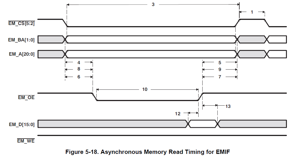
    My recommendation is to align your timing as per “ Timing Requirements for EMIF Asynchronous Memory ” mentioned in C5515 datasheet “SPRS645F “ table 5-18 ,Table 5-19. Refer to the Asynchronous read timing diagram 5-18 in the same document.


    Based on this information, you can configure ACSnCR2 register to achieve minimum sampling time possible. The one which you are referring in user guide is an example and I do not think it specifies the minimum timing requirement.


    I understand that this is your custom hardware platform, is this correct ? have you tried with your minimum sampling time requirement ?


    Regards

    Vasanth

  • From the timing diagram you show, the minimum read cycle time is parameters (1) + (3).  From the definitions of these parameters in Table 5-19, minimum read time is (TA) + (RS + RST + RH)

    Where:

    TA = R_TURNAROUND

    RS = R_SETUP

    RST = R_STROBE

    RH = R_HOLD

    I believe the minimum for RS, RST, and RH is 1.  I think for successive reads, the minimum is 0.  In theory then, the minimum is 3 clock cycles.  In practice, the minimum I can achieve is 5 clocks.

    Maybe that is my problem.  Is the turn around time 0 for successive reads?

    For my hardware, I am using C5515 eZDSP USB stick for testing purposes.  

    Chuck

  • If its successive read, then no Turnaround cycles are required.

    Below is the snapshot from User guide for your reference.

    Hope this helps.

    Regards

     Vasanth

  • Hi Vasanth,

    Thanks for trying, but It looks like the minimum clocks for R_SETUP and R_HOLD is 2. I don't see any other explanation.

    My impression is that the EMIF was mainly designed for interfacing to memory, not high-speed peripheral devices. I can work around it, but I got better performance from a older C54 that had externally mapped I/O space.

    Chuck