This thread has been locked.

If you have a related question, please click the "Ask a related question" button in the top right corner. The newly created question will be automatically linked to this question.

CCS/TMS320C5545: Code composer V7 step by step lowpass fir filter implementation guide

Part Number: TMS320C5545

Tool/software: Code Composer Studio

Hi,

I'm beginner with this dsp stuff, I want to implement fir lowpass filter on dsp c5545 boosterpack, can you provide me a step by step guide instructions to do it using code composer studio v6. Thanks in advance

I'm giving analog input through line in, is there a function or c code to obtain the input data samples to use it in my fir function? I would like to run the code on ccs and hear the output from headphone output

  • Hi,

    The C55 team is notified. They will post their feedback directly here.

    Best Regards,
    Yordan
  • Hi, can some one shed some light on this. We are in a critical stage and need to implement the above mentioned dsp filter asap. Thanks
  • V Pot,

    Check out this e2e thread referencing the C55x teaching ROM e2e.ti.com/.../600411
    Also, you will also want to peruse the DSPLIB for C55x which can be found here processors.wiki.ti.com/.../C55x_DSPLIB_FAQ. This package has a bunch of DSP routines.

    Lali
  •  Lali,

    Thanks for your time. I tried building an example project from c5545bp_software folder. its giving me following attached errors. Can you please help me fix that ? thanks.

  • V Pot,

    Please check in your project properties that its pointing correctly to C55XXCSL_LP.

    Lali
  • I can't find c55xxcsl_lp.lib to link, where can i find it? it's not in the c55xxcsl_lp folder
  • V Pot,

    Once you build the project C55XXCSL_LP, it will be in its debug folder.

    Lali

  •  hi lali,

    I tried to build the project buts showing dsp/bios not installed error. but I installed the exact version and its still same error. and i don't see the lib file in debug. see the attachment

  • V Pot,

    Did you register the BIOS package with CCS? If not, your environment will not be aware of the BIOS package to use.
    The screenshot below shows a PDK package in my machine that isn't registered. Its irrelevant in your case, but I'm just trying to illustrate the pop-up window asking you to register a new component that you installed in your machine.

    Lali

  •  yes i've installed it, when i opened ccs it asked me to do so and i did. also you can see the dsp/bios assigned is same versions as in error. see attached

  • Do you have the BIOS package listed when you go to  Window>preferences>Code Composer Studio>Products?

  •  no i don't see them listed, when I click rediscover list came up and I tried to install, but it throws following errors while installing. see attached

  • V Pot,

    That indicates that you do not have the package registered with CCS.
    Can you ONLY select the bios_5_42_02_10 package and install? does it complete?

    Lali
  • I'm able to build now. thanks

    one more question. Now I'm able to run the example project audio line in...I want to implement a c program that has fir code in it, all it does is multiply the sample data with their corresponding coefficients from matlab. so my question is how to get the sampling data? i mean the data converted by adc (i'm connecting my input to line in) . can you point me to a function or c code to get the sample data?
  • V Pot,

    Take a look at the Boosterpack sample code
    C:\ti\c55_lp\c55_csl_3.08\demos\out_of_box\c5545\c5545bp_software_01.01.00.00\source_code\c55xx_diagnostics\board\diag\audio_test

    This has a line-in demo that shows how to sample the audio.

    Lali
  • Hi lali,

    I ran the audio line in example with audio line in cable connected to my pc on other end and i was playing music on my pc. I then ran the code, its getting stuck in the while loop as follows while waiting to receive data. All my jumper settings and cables were set as mentioned in the user guide.

    void I2S_readLeft(Int16* data)
    {
    ioport CSL_I2sRegs *regs;

    regs = hI2s->hwRegs;
    while((0x08 & regs->I2SINTFL) == 0); // Wait for receive interrupt to be pending
    *data = regs->I2SRXLT1 ; // 16 bit left channel receive audio data
    }
  • hi lali,
    can you comment on above error? thanks
  • V Pot,

    What instructions did you follow?
    Do you have the jumpers as in section A.1 of www.ti.com/.../sprui92.pdf
    Are you trying to run A.1.2.1.7.2 Test Execution?
    Did any of the other tests work?
    Did you compile the code and load on the DSP or are you trying to run the bootimg.bin that comes in the SD card which is in the box?
    Do you have the correct macro for the C5545 defined in csl_general.h if you did compile the code and load?

    Lali
  • Hi lali,

    yes jumpers came in default settings as they mentioned in A.1,

    yes i'm trying to run the audio line in loop back demo,

    I've tried audio mic in loop back test as well, same issue it gets struck in the while loop as in my previous reply above.

    -I'm using teraterm terminal and ccs debug mode to run code on the emulator i guess?

    -yes it has following defined in csl_general.h

    -#define C5545_BSTPCK, 

    -#define CHIP_C5545

    -Following is the result of test connection made to c5545 boosterpack to ccs via XDS100v1 USB Debug Probe.

    [Start: Texas Instruments XDS100v1 USB Debug Probe_0]

    Execute the command:

    %ccs_base%/common/uscif/dbgjtag -f %boarddatafile% -rv -o -F inform,logfile=yes -S pathlength -S integrity

    [Result]


    -----[Print the board config pathname(s)]------------------------------------

    C:\Users\Vissu\AppData\Local\TEXASI~1\CCS\
    ti\1\0\BrdDat\testBoard.dat

    -----[Print the reset-command software log-file]-----------------------------

    This utility has selected a 100- or 510-class product.
    This utility will load the adapter 'jioserdesusb.dll'.
    The library build date was 'Jul 27 2016'.
    The library build time was '18:31:37'.
    The library package version is '6.0.407.3'.
    The library component version is '35.35.0.0'.
    The controller does not use a programmable FPGA.
    The controller has a version number of '4' (0x00000004).
    The controller has an insertion length of '0' (0x00000000).
    This utility will attempt to reset the controller.
    This utility has successfully reset the controller.

    -----[Print the reset-command hardware log-file]-----------------------------

    The scan-path will be reset by toggling the JTAG TRST signal.
    The controller is the FTDI FT2232 with USB interface.
    The link from controller to target is direct (without cable).
    The software is configured for FTDI FT2232 features.
    The controller cannot monitor the value on the EMU[0] pin.
    The controller cannot monitor the value on the EMU[1] pin.
    The controller cannot control the timing on output pins.
    The controller cannot control the timing on input pins.
    The scan-path link-delay has been set to exactly '0' (0x0000).

    -----[The log-file for the JTAG TCLK output generated from the PLL]----------

    There is no hardware for programming the JTAG TCLK frequency.

    -----[Measure the source and frequency of the final JTAG TCLKR input]--------

    There is no hardware for measuring the JTAG TCLK frequency.

    -----[Perform the standard path-length test on the JTAG IR and DR]-----------

    This path-length test uses blocks of 64 32-bit words.

    The test for the JTAG IR instruction path-length succeeded.
    The JTAG IR instruction path-length is 38 bits.

    The test for the JTAG DR bypass path-length succeeded.
    The JTAG DR bypass path-length is 1 bits.

    -----[Perform the Integrity scan-test on the JTAG IR]------------------------

    This test will use blocks of 64 32-bit words.
    This test will be applied just once.

    Do a test using 0xFFFFFFFF.
    Scan tests: 1, skipped: 0, failed: 0
    Do a test using 0x00000000.
    Scan tests: 2, skipped: 0, failed: 0
    Do a test using 0xFE03E0E2.
    Scan tests: 3, skipped: 0, failed: 0
    Do a test using 0x01FC1F1D.
    Scan tests: 4, skipped: 0, failed: 0
    Do a test using 0x5533CCAA.
    Scan tests: 5, skipped: 0, failed: 0
    Do a test using 0xAACC3355.
    Scan tests: 6, skipped: 0, failed: 0
    All of the values were scanned correctly.

    The JTAG IR Integrity scan-test has succeeded.

    -----[Perform the Integrity scan-test on the JTAG DR]------------------------

    This test will use blocks of 64 32-bit words.
    This test will be applied just once.

    Do a test using 0xFFFFFFFF.
    Scan tests: 1, skipped: 0, failed: 0
    Do a test using 0x00000000.
    Scan tests: 2, skipped: 0, failed: 0
    Do a test using 0xFE03E0E2.
    Scan tests: 3, skipped: 0, failed: 0
    Do a test using 0x01FC1F1D.
    Scan tests: 4, skipped: 0, failed: 0
    Do a test using 0x5533CCAA.
    Scan tests: 5, skipped: 0, failed: 0
    Do a test using 0xAACC3355.
    Scan tests: 6, skipped: 0, failed: 0
    All of the values were scanned correctly.

    The JTAG DR Integrity scan-test has succeeded.

    [End: Texas Instruments XDS100v1 USB Debug Probe_0]

    -I've also attached the ccs and teraterm terminal window

    -Also I see this error "No source available "0xff570e" "

  • Hi Lali,
    any views on the above post? Thanks.
  • V Pot,
    Do any of the other non-audio related examples work? The JTAG scan shows that there are no emulator issues.
    Lali
  • Hi lali,

    i tried compiling boostc5545_diag_test example and it throws following errors. I'm not sure of JTAG scan but I'm using just the micro-usb to connect booster pack and pc via debug port on boosterpack

  • Lali,

    I just tried the led test example and it worked perfectly fine, i can see the 3 leds toggling.  

    And I also figured that audio is playing through the headphone jack of the booster pack even the power is turned off, but only when i insert my earphone jack loosely into the headphone jack of the boosterpack. if I push it completely i won't hear anything.

    Only time i hear audio when my earphone plug is tightly inserted is when I turn on the power and select audio line -in by selecting s4 switch on the board. But when i run the audio loop back test via ccs connected to booster pack it would make a clicking sound once and nothing plays after. These weird issues are really annoying. Please help! 

  • V Pot,

    The audio playing with the power off is a known issue (see pg 19 of http://www.ti.com/lit/ug/sprui90/sprui90.pdf)

    What type of headphone are you using? #1 or #2 above. The headphone that comes in the kit is the one that will work with the headphone jack on the BOOT5545ULP.

    Lali

  • Lali,

    I've used bose soundsport in-ear which is 1 above and also used the earphones came with booster pack ,same result. When I run the audio line in loop back test, it just makes a clicking sound for less than a sec and nothing plays. That's my issue. but audio loopback test works if i try just onboard by clicking sw4 and sw2 by choosing audio line in. but it doesn't work by running the demo using ccs as it worked for led example. Do you think its a codec malfunction? Do you recommend ordering another boosterpack?

  • V Pot,

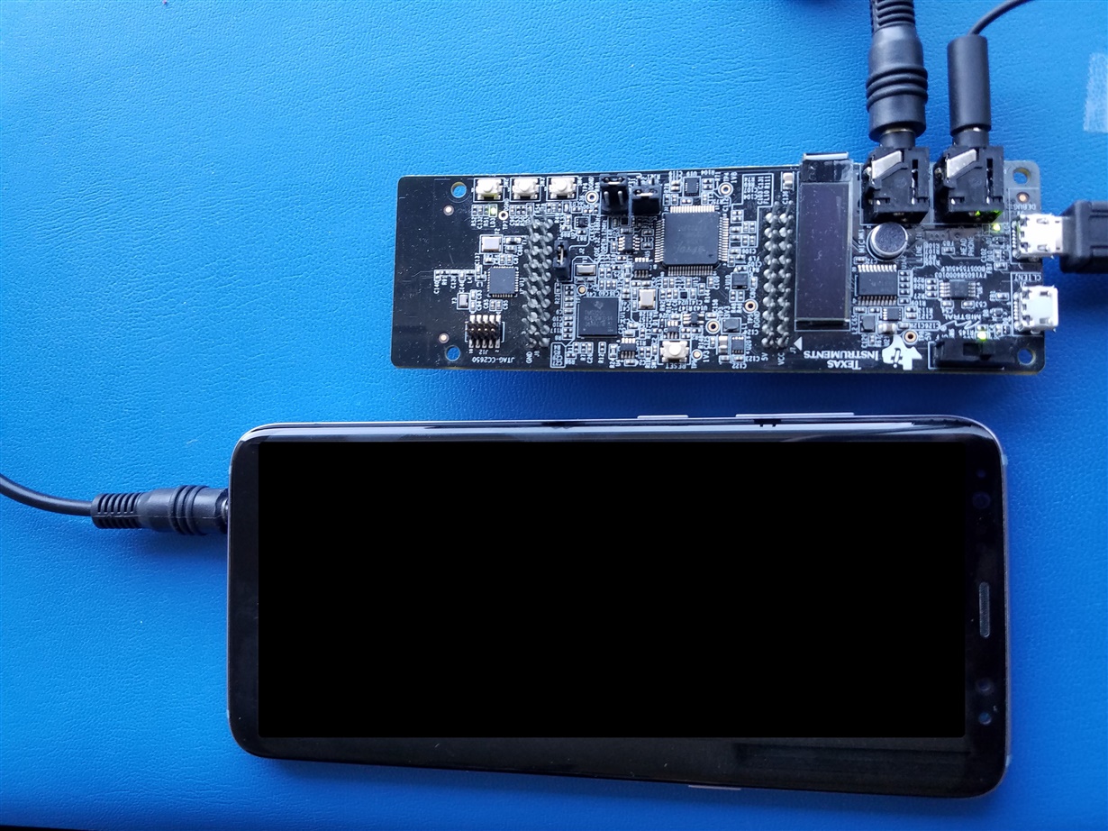
    Please try with the attached .out and see if it works. It worked on my platform as connected below. Please note that after loading and running the .out in CCS, it took about 10 seconds before I started hearing the looped back audio via the headphones. I just played a song with Spotify on my phone piped to the BoosterPack and I could hear it on my headphones.

    Here's a pic of my setup.

    The console output in CCS should look like this while the audio is playing.

    Lali

    /cfs-file/__key/communityserver-discussions-components-files/791/6675.audio_5F00_line_5F00_in_5F00_loopback_5F00_test.out

  • Lali,

    Thanks for the file. yes it worked now with this .out file
    1) so what was the issue with my .out file?
    2)audio sounds little distorted when running your .out file , is that because you have low sample rate in your build code?
    3) and audio played for few seconds only. is that because you gave only few seconds to play in your c code that you build?
    4)Now how can I get the .out file based on my time requirement and sample rate?
  • V Pot,

    1) Don't know. Lets find out.

    2) Its the default sampling rate. No changes.

    3) This is diagnostic code. You will have to manipulate the source file for a longer play length.

    4) See #3.

    Does your CCS workspace look as below?

    Do you have your csl_general.h setup like the attached file specifically for the? #define C5545_BSTPCK.

    Keep in mind that you have to rebuild C55XXCSL_LP once the csl_general.h is modified, pror to building the audio_line_in_loop back_test project.

    Lali

    /cfs-file/__key/communityserver-discussions-components-files/791/3036.1122.csl_5F00_general.h

  •  1)My workspace doesn't have BF_rt_bios, please the attached pic for better understanding.

    2)So I changed my csl_general to the one you provided. now i'm getting build errors as shown in pic, these errors are from cslr_sysctrl.h file because you commented out definitions of chips like c5517 in csl_general.h, we probably need to change the cslr_sysctrl.h file accordingly to avoid build errors. am i correct? if so please provide me the right cslr_sysctrl.h file

  • V Pot,

    You should not need to modify any of these files. I think there is fundamentally wrong with your environment.
    Can you please grab the latest CSL 3.08 from here software-dl.ti.com/.../index_FDS.html

    I noticed that you are using 3.06.
    Also you don't need BF_rt_bios. Thats just left over from another project in my workspace. You only need the highlighted projects in your workspace.

    Lali
  •  Lali,

    thanks that fixed the problem, but i still have one more issue left. the audio is distorting at high amplitudes. I changed the the time of play and sample rate in the code to 44000 as shown in pic attached. but it still distorts.

  • V Pot,

    You will have to manipulate the AIC3206 settings as well to suit the new sampling rate inside AIC3206_loop_linein()
    The distortion could be due to a rate mismatch.

    Lali
  • Lali,
    I see. can you please point me what exactly that need to be changed? I see there are several setting being written in that aic3206_loop_linein()
    let's say im interested in 44000 samples per sec(CD quality)
  • V Pot,

    I'm unaware of the exact changes. Please check out the device datasheet and the relevant registers that need to be configured www.ti.com/.../TLV320AIC3206

    You can also ask AIC3206 specific questions on the device forum e2e.ti.com/.../

    Check out the file C:\ti\c55_lp\c55_csl_3.08\demos\out_of_box\c5545\c5545bp_software_01.01.00.00\source_code\c55xx_diagnostics\board\diag\audio_test\audio_mic_in_loopback_test\src\audio_mic_in_loopback_test.c

    ~line 90. I think this configures for 48KHz

    Lali
  • Lali,

    Thanks for your help. You are a life saver brother. I'll contact the audio guys regarding the codec.
  • Lali,

    I'm running the fir filter hamming window order 161 bandpass with pass frequency range 20hz-200hz,  but out put doesn't sound like the filter is working. it's just distorted output. following is the code and 162 coefficients.

    coeff:-0.00035514,-0.0003342,-0.00031519,-0.0002975,-0.00028048,-0.00026346,-0.00024575,-0.00022664,-0.00020539,-0.00018126,-0.00015351,-0.00012138,-8.4119e-05,-4.0977e-05,8.7845e-06,6.5896e-05,0.00013107,0.00020499,0.00028834,0.00038174,0.00048581,0.00060111,0.00072817,0.00086749,0.0010195,0.0011846,0.0013631,0.0015553,0.0017614,0.0019817,0.0022161,0.0024647,0.0027276,0.0030046,0.0032955,0.0036002,0.0039183,0.0042495,0.0045934,0.0049494,0.005317,0.0056956,0.0060845,0.006483,0.0068902,0.0073053,0.0077274,0.0081555,0.0085887,0.0090258,0.0094659,0.0099077,0.01035,0.010792,0.011233,0.01167,0.012103,0.012531,0.012952,0.013366,0.013771,0.014165,0.014548,0.014918,0.015275,0.015617,0.015943,0.016253,0.016544,0.016817,0.017071,0.017304,0.017515,0.017705,0.017873,0.018018,0.018139,0.018237,0.01831,0.018359,0.018384,0.018384,0.018359,0.01831,0.018237,0.018139,0.018018,0.017873,0.017705,0.017515,0.017304,0.017071,0.016817,0.016544,0.016253,0.015943,0.015617,0.015275,0.014918,0.014548,0.014165,0.013771,0.013366,0.012952,0.012531,0.012103,0.01167,0.011233,0.010792,0.01035,0.0099077,0.0094659,0.0090258,0.0085887,0.0081555,0.0077274,0.0073053,0.0068902,0.006483,0.0060845,0.0056956,0.005317,0.0049494,0.0045934,0.0042495,0.0039183,0.0036002,0.0032955,0.0030046,0.0027276,0.0024647,0.0022161,0.0019817,0.0017614,0.0015553,0.0013631,0.0011846,0.0010195,0.00086749,0.00072817,0.00060111,0.00048581,0.00038174,0.00028834,0.00020499,0.00013107,6.5896e-05,8.7845e-06,-4.0977e-05,-8.4119e-05,-0.00012138,-0.00015351,-0.00018126,-0.00020539,-0.00022664,-0.00024575,-0.00026346,-0.00028048,-0.0002975,-0.00031519,-0.0003342,-0.00035514

    code:-

    for ( sec = 0 ; sec < 30 ; sec++ )
    {
    for ( msec = 0 ; msec < 1000 ; msec++ )
    {
    for ( sample = 0 ; sample < 16 ; sample++ )
    {
    /* Read 16-bit left channel Data */
    I2S_readLeft(&data1);

    /* Read 16-bit right channel Data */
    I2S_readRight(&data2);


    // As a new sample is received put it in two places
    x[index1] = data1;
    x[index2] = data1;
    z[index1] = data2;
    z[index2] = data2;
    y1new=0;
    y2new=0;
    for(i=0;i<N;i++){
    y1new = y1new + coeff[i]*x[index2-i];
    y2new = y2new + coeff[i]*z[index2-i];
    }

    index1 = (index1+1)%N;
    index2 = index1+N;
    data1=y1new;
    data2=y2new;
    /* Write 16-bit left channel Data */
    I2S_writeLeft(data1);

    /* Write 16-bit right channel Data */
    I2S_writeRight(data2);
    }
    if(sw3Pressed == TRUE)
    {
    break;
    }

    }
    if(sw3Pressed == TRUE)
    {
    break;
    }

    }

    2)

    also if you look at the default audio line in or mic in c code you sent, there is this loop below. why there is msec? and why sampling rate is 48 for 48khz?

    for ( sec = 0 ; sec < 5 ; sec++ )
    // {
    // for ( msec = 0 ; msec < 5000 ; msec++ )
    // {
    // for ( sample = 0 ; sample < 48 ; sample++ )
    // {
    // /* Read 16-bit left channel Data */
    // I2S_readLeft(&data1);
    //
    // /* Read 16-bit right channel Data */
    // I2S_readRight(&data2);
    //
    // /* Write 16-bit left channel Data */
    // I2S_writeLeft(data1);
    //
    // /* Write 16-bit right channel Data */
    // I2S_writeRight(data2);
    // }
    // if(sw3Pressed == TRUE)
    // {
    // break;
    // }
    //
    // }
    // if(sw3Pressed == TRUE)
    // {
    // break;
    // }
    //
    // }


  • Lali,

    can you look at my above post, also I think the distorted filtering is due to the latency issue , how to make sure no over/under runs occur? or avoid the transmit buffer running dry. thanks in advance
  • V Pot,

    Will have to get back to you.

    Lali
  • Lali,
    Sure, and for your reference here is a TI implementation of stethoscope on c5515 with fir bandpass hamming window 161 and heart beat detection in realtime without latency. that's what the document is claiming. so i should also be able to run the filter without noticeable latency issues. Refer 3.2 & 3.3
    www.ti.com/.../sprab38a.pdf
  • lali,

    any solution yet for my problem?
  • Still working on it. Need to check with some colleagues internally.

    Lali
  • Hi V Pot,

    There are 1000 milliseconds per second. If the sampleing rate is 48Khz, then there are 48 samples each millisecond. The above code should be sec < 5 and msec < 1000 and sample < 48.

    In your implementation, you are assuming 16Khz (sample < 16). If you meant 48khz, then it should be (sample < 48).

    Ming 

  •   int N=269;
    	    int i,n;
    	    int index1=0;
    	    int index2=N;
    	    float x[2*269];
    	    float z[2*269];
    	    float y1new,y2new;
    	    I2S_writeLeft(0);
    		I2S_writeRight(0);
    		for(n=0;n<N;n++){
    			coeff[n]=round(coeff[n]*256);
    		}
    	    for ( sec = 0 ; sec < 30 ; sec++ )
    	    	    {
    	    	        for ( msec = 0 ; msec < 1000 ; msec++ )
    	    	        {
    	    	            for ( sample = 0 ; sample < 16 ; sample++ )
    	    	            {
    	    	                /* Read 16-bit left channel Data */
    	    	            	I2S_readLeft(&data1);
    
    	    	                /* Read 16-bit right channel Data */
    	    	                I2S_readRight(&data2);
    
    
    	    	                // As a new sample is received put it in two places
    	    	                x[index1] = data1;
    	    	                x[index2] = data1;
    	    	                z[index1] = data2;
    	    	                z[index2] = data2;
    	    	                y1new=0;
    	    	                y2new=0;
    	    	                for(i=0;i<N;i++){
    	    	                y1new = y1new + coeff[i]*x[index2-i];
    	    	                y2new = y2new + coeff[i]*z[index2-i];
    	    	                }
    
    	    	                index1 = (index1+1)%N;
    	    	                index2 = index1+N;
                                data1=round(y1new/256);
                                data2=round(y2new/256);
    	    	                /* Write 16-bit left channel Data */
    	    	                I2S_writeLeft(data1);
    
    	    	                /* Write 16-bit right channel Data */
    	    	                I2S_writeRight(data2);
    	    	            }
    	    	            if(sw3Pressed == TRUE)
    	    	            {
    	    	            	break;
    	    	            }
    
    	    	        }
    	                if(sw3Pressed == TRUE)
    	                {
    	                	break;
    	                }
    
    	    	    }

    hello ming,

    thanks for your reply.

    1)no I want to tryout different sample rates like 16000hz, 4000hz and 1000hz. i'm trying to implement an fir bandpass with hammingwindow like ti implemented in the article below on c5515, Refer 3.2 & 3.3

    2)C5545 is a fixed point dsp right? I tried scaling the coeff accordingly by multiplying with 256 and dividing later. please refer to the code below. I'm listening distortion if run the code.

    3) is that due to the latency induced by c5545? or am i doing anything wrong?

  • Hi V Pot,

    1) Make sure you change the Audio codec settings for the same sampling rate.

    2) Yes. C5545 is a fixed point DSP, but the way we do the filtering is using the Q15 (1 bit sign and 15 bit data, the value is between -1 and 1, i.e. the decimal point is after bit 15). Both data and coefficients are presented in Q15 format. To do the filtering algorithm, you can do the following:

    long res_q30, res_q15;

    int data_q15, coef_q15;

    res_q30 = (long)data_q15*coef_q15;

    res_q15 = res_q30>>15;

    3) Most likely is the incorrect filtering algorithm or the not using Ping Pong buffers (one is used for receiving data, the other is used for data processing). You can use the Audio codec loopback example as the start point (ccs_v6.x_examples\i2s\CSL_I2S_AudioCodec_DMA), then add your filtering algorithm to UserAlgorithm() in AudioCodec_DMA.c.

    You can also download the following audio filtering demo for C5515 eZDSP Kit from https://code.google.com/archive/p/c5505-ezdsp/downloads

    https://storage.googleapis.com/google-code-archive-downloads/v2/code.google.com/c5505-ezdsp/C5515_eZdsp_Audio_Filter_Demo1.zip

    The filtering algorithm is implemented in assembly (fir() in fir.asm). The main loop is in main_bypass1.c. The I2S used in C5515 ezdsp is different than the one used in C5545 ezdsp though.

    Both examples are using Ping-Pong Buffers.

    Ming


  • Typo, the res_q15 should be int, not long.

    Ming
  • Special Considerations When Using MAC for Q15

    int dotp(const int *x, const int *y, unsigned int n)
    {
    unsigned int i;
    long sum=0;

    for(i=0; i<=n−1; i++)
    sum += (long)x[i] * y[i];
    return (int)((sum>>15) & 0x0000FFFFL);
    }

    Ming
  • Hi Ming,

    1) yes i've set the codec for 8000 sampling rate, and my matlab coeffs are also calculated at 8000 sampling rate.

    2) I don't think i've implementation issues. please look at the code below, i'm using circular buffer with twice length. Also i've used the audio loop back test example code for c5545 and added my filtering code to it. default loopback test code provided by ti uses Int16 for input data(right & left) and Int16 for output as well. I've converted the floating point coeff values from matlab to int16, please see code below. I'm able to hear neat output by running the code.

    but my issues are it doesn't sound like the filter i designed (band pass 20-200hz), i'm able to hear frequencies upto 4000hz passing through my filter. if you plot my coeff it shows you a perfect bandpass between 20-200hz. i don't know why my output is not behaving as it should be.

    /*
     * Copyright (c) 2016, Texas Instruments Incorporated
     * All rights reserved.
     *
     * Redistribution and use in source and binary forms, with or without
     * modification, are permitted provided that the following conditions
     * are met:
     *
     * *  Redistributions of source code must retain the above copyright
     *    notice, this list of conditions and the following disclaimer.
     *
     * *  Redistributions in binary form must reproduce the above copyright
     *    notice, this list of conditions and the following disclaimer in the
     *    documentation and/or other materials provided with the distribution.
     *
     * *  Neither the name of Texas Instruments Incorporated nor the names of
     *    its contributors may be used to endorse or promote products derived
     *    from this software without specific prior written permission.
     *
     * THIS SOFTWARE IS PROVIDED BY THE COPYRIGHT HOLDERS AND CONTRIBUTORS "AS IS"
     * AND ANY EXPRESS OR IMPLIED WARRANTIES, INCLUDING, BUT NOT LIMITED TO,
     * THE IMPLIED WARRANTIES OF MERCHANTABILITY AND FITNESS FOR A PARTICULAR
     * PURPOSE ARE DISCLAIMED. IN NO EVENT SHALL THE COPYRIGHT OWNER OR
     * CONTRIBUTORS BE LIABLE FOR ANY DIRECT, INDIRECT, INCIDENTAL, SPECIAL,
     * EXEMPLARY, OR CONSEQUENTIAL DAMAGES (INCLUDING, BUT NOT LIMITED TO,
     * PROCUREMENT OF SUBSTITUTE GOODS OR SERVICES; LOSS OF USE, DATA, OR PROFITS;
     * OR BUSINESS INTERRUPTION) HOWEVER CAUSED AND ON ANY THEORY OF LIABILITY,
     * WHETHER IN CONTRACT, STRICT LIABILITY, OR TORT (INCLUDING NEGLIGENCE OR
     * OTHERWISE) ARISING IN ANY WAY OUT OF THE USE OF THIS SOFTWARE,
     * EVEN IF ADVISED OF THE POSSIBILITY OF SUCH DAMAGE.
     *
     */
    
    /*! \file audio_line_in_loopback_test.c
    *
    *   \brief Functions that configure the audio codec regsiters for the audio
    *          line in loopback operation.
    *
    */
    
    #include "audio_line_in_loopback_test.h"
    #include "audio_common.h"
    #include "../../../build/boostC5545/audio_line_in_loopback_test/coeff"
    #include <math.h>
    extern TEST_STATUS AIC3206_loop_linein(void *testArgs);
    
    /**
     *
     * \brief This function configures all audio codec registers for
     *        line in loopback test
     *
     * \param    testArgs   [IN]   Test arguments
     *
     * \return
     * \n      TEST_PASS  - Test Passed
     * \n      TEST_FAIL  - Test Failed
     *
     */
    TEST_STATUS AIC3206_loop_linein(void *testArgs)
    {
    	    Int16 sec, msec;
    	    Int16 sample, data1, data2;
    	    Int32 output1,output2;
    
    	    /* Configure AIC3206 */
    	    AIC3206_write( 0,  0x00 );  // Select page 0
    	    AIC3206_write( 1,  0x01 );  // Reset codec
    	    C55x_delay_msec(1);  		// Wait 1ms after reset
    	    AIC3206_write( 0,  0x01 );  // Select page 1
    	    AIC3206_write( 1,  0x08 );  // Disable crude AVDD generation from DVDD
    	    AIC3206_write( 2,  0x01 );  // Enable Analog Blocks, use LDO power
    	    AIC3206_write( 123,0x05 );  // Force reference to power up in 40ms
    	    C55x_delay_msec(40); 		// Wait at least 40ms
    	    AIC3206_write( 0,  0x00 );  // Select page 0
    
    	    /* PLL and Clocks config and Power Up  */
    	    AIC3206_write( 27, 0x0d );  // BCLK and WCLK are set as o/p; AIC3206(Master)
    	    AIC3206_write( 28, 0x00 );  // Data ofset = 0
    	    AIC3206_write( 4,  0x03 );  // PLL setting: PLLCLK <- MCLK, CODEC_CLKIN <-PLL CLK
    	    AIC3206_write( 6,  0x07 );  // PLL setting: J=7
    	    AIC3206_write( 7,  0x06 );  // PLL setting: HI_BYTE(D=1680)
    	    AIC3206_write( 8,  0x90 );  // PLL setting: LO_BYTE(D=1680)
    	    AIC3206_write( 30, 0x88 );  // For 32 bit clocks per frame in Master mode ONLY
    	                               	// BCLK=DAC_CLK/N =(12288000/8) = 1.536MHz = 32*fs
    	    AIC3206_write( 5,  0x91 );  // PLL setting: Power up PLL, P=1 and R=1
    		C55x_delay_msec(1); 		// Wait for PLL to come up
    		AIC3206_write( 13, 0x00 );  // Hi_Byte(DOSR) for DOSR = 128 decimal or 0x0080 DAC oversamppling
    		AIC3206_write( 14, 0x80 );  // Lo_Byte(DOSR) for DOSR = 128 decimal or 0x0080
    		AIC3206_write( 20, 0x80 );  // AOSR for AOSR = 128 decimal or 0x0080 for decimation filters 1 to 6
    		AIC3206_write( 11, 0x87 ); // Power up NDAC and set NDAC value to 7
    		AIC3206_write( 12, 0x8C ); // Power up MDAC and set MDAC value to 12
    		AIC3206_write( 18, 0x87 ); // Power up NADC and set NADC value to 7
    		AIC3206_write( 19, 0x8C ); // Power up MADC and set MADC value to 12
    
    
    	    /* DAC ROUTING and Power Up */
    	    AIC3206_write( 0,  0x01 );  // Select page 1
    	    AIC3206_write( 12, 0x08 );  // LDAC AFIR routed to HPL
    	    AIC3206_write( 13, 0x08 );  // RDAC AFIR routed to HPR
    	    AIC3206_write( 0,  0x00 );  // Select page 0
    	    AIC3206_write( 64, 0x02 );  // Left vol=right vol
    	    AIC3206_write( 65, 0x20 );  // Left DAC gain to 0dB VOL; Right tracks Left
    	    AIC3206_write( 63, 0xd4 );  // Power up left,right data paths and set channel
    	    AIC3206_write( 0,  0x01 );  // Select page 1
    	    AIC3206_write( 16, 0x00 );  // Unmute HPL , 0dB gain
    	    AIC3206_write( 17, 0x00 );  // Unmute HPR , 0dB gain
    	    AIC3206_write( 9 , 0x30 );  // Power up HPL,HPR
    	    C55x_delay_msec(1 );        // Wait 1 msec
    
    	    /* ADC ROUTING and Power Up */
    	    AIC3206_write( 0,  0x01 );  // Select page 1
    	    AIC3206_write( 52, 0x30 );  // STEREO 1 Jack
    	                               	// IN2_L to LADC_P through 40 kohm
    	    AIC3206_write( 55, 0x33 );  // IN2_R to RADC_P through 40 kohmm
    	    AIC3206_write( 54, 0x03 );  // CM_1 (common mode) to LADC_M through 40 kohm
    	    AIC3206_write( 57, 0xc0 );  // CM_1 (common mode) to RADC_M through 40 kohm
    	    AIC3206_write( 59, 0x00 );  // MIC_PGA_L unmute
    	    AIC3206_write( 60, 0x00 );  // MIC_PGA_R unmute
    	    AIC3206_write( 0,  0x00 );  // Select page 0
    	    AIC3206_write( 81, 0xc0 );  // Powerup Left and Right ADC
    	    AIC3206_write( 82, 0x00 );  // Unmute Left and Right ADC
    	    AIC3206_write( 0,  0x00 );  // Select page 0
    	    C55x_delay_msec(1 );        // Wait 1 msec
    
    	    /* Initialize I2S */
    	    initialise_i2s_interface();
    	    gpio_interrupt_initiliastion();
    
    	    /*Circular Buffer FIR Implementation*/
    
    	    int N=269;
    	    int i,n;
    	    int index1=0;
    	    int index2=N;
    	    Int16 x[2*269];
    	    Int16 z[2*269];
    	    Int32 y1new,y2new;
    	    Int16 a[10000];
    	    int k=0;
    	    I2S_writeLeft(0);
    		I2S_writeRight(0);
    		for(n=0;n<N;n++){
    			coeff1[n]=round(coeff[n]*8);
    		}
    	    for ( sec = 0 ; sec < 60 ; sec++ )
    	    	    {
    	    	        for ( msec = 0 ; msec < 1000 ; msec++ )
    	    	        {
    	    	            for ( sample = 0 ; sample < 8 ; sample++ )
    	    	            {
    	    	                /* Read 16-bit left channel Data */
    	    	            	I2S_readLeft(&data1);
    
    	    	                /* Read 16-bit right channel Data */
    	    	                I2S_readRight(&data2);
    
    
    	    	                // As a new sample is received put it in two places
    	    	                x[index1] = data1;
    	    	                x[index2] = data1;
    	    	                z[index1] = data2;
    	    	                z[index2] = data2;
    	    	                y1new=0;
    	    	                y2new=0;
    	    	                for(i=0;i<N;i++){
    	    	                y1new = y1new + coeff1[i]*x[index2-i];
    	    	                y2new = y2new + coeff1[i]*z[index2-i];
    	    	                }
    
    	    	                index1 = (index1+1)%N;
    	    	                index2 = index1+N;
                                output1=round(y1new/8);
                                output2=round(y2new/8);
                                a[k]=output1;
                                k=k+1;
                               // printf("%s\n", output1);
    	    	                /* Write 16-bit left channel Data */
    	    	                I2S_writeLeft(data1);
    
    	    	                /* Write 16-bit right channel Data */
    	    	                I2S_writeRight(data2);
    	    	            }
    	    	            if(sw3Pressed == TRUE)
    	    	            {
    	    	            	break;
    	    	            }
    
    	    	        }
    	                if(sw3Pressed == TRUE)
    	                {
    	                	break;
    	                }
    
    	    	    }
    
    	   //*****filtering ends here**********//
    
    
    	    I2S_close(hI2s);    // Disble I2S
    	    AIC3206_write( 1, 0x01 );  // Reset codec
    
    	    return 0;
    }
    
    /**
     *
     * \brief This function used to initialise i2c interface and run
     *        audio line in loopback test
     *
     * \param    testArgs   [IN]   Test arguments
     *
     * \return
     * \n      TEST_PASS  - Test Passed
     * \n      TEST_FAIL  - Test Failed
     *
     */
    static TEST_STATUS run_audio_line_in_loopback_test(void *testArgs)
    {
    	 Int16 retVal;
    	 Uint8  c = 0;
    
    	 /* Enable clocks to all peripherals */
    	 CSL_SYSCTRL_REGS->PCGCR1 = 0x0000;
    	 CSL_SYSCTRL_REGS->PCGCR2 = 0x0000;
    
    	 retVal =  SYS_setEBSR(CSL_EBSR_FIELD_PPMODE,
    			               CSL_EBSR_PPMODE_1);    // Configure Parallel Port for I2S2
    	 retVal |= SYS_setEBSR(CSL_EBSR_FIELD_SP1MODE,
    	                          CSL_EBSR_SP1MODE_1);  // Serial Port mode 1 (I2S1 and GP[11:10]).
    
    	 retVal = initialise_i2c_interface(testArgs);
    	 if(retVal != 0)
    	 {
    		 C55x_msgWrite("I2C initialisation failed\n\r");
    		 return (TEST_FAIL);
    	 }
    
    	 C55x_msgWrite( "Test Receives audio samples from LINE IN and output the same\n\r"
    			        "on HEADPHONE port\n\n\r");
    
    	 C55x_msgWrite("Connect headset to the HEADPHONE port of the BoosterPack\n\n\r");
    	 C55x_msgWrite("Connect a LINE-IN cable between the audio port of the\n\r"
    			       "Test PC and LINE IN of the BoosterPack\n\n\r");
    
    	 C55x_msgWrite("Play any audio file from the Test PC and Check \n\r"
    			       "Audio from the headset connected to BoosterPack\n\n\r");
    
    	 retVal = AIC3206_loop_linein(testArgs);
    	 if(retVal != 0)
    	 {
    		 return (TEST_FAIL);
    	 }
    
    #ifdef USE_USER_INPUT
    
    	 C55x_msgWrite("Press Y/y if the Audio stream from LINE IN is\n\r"
    			       "observed at the headset connected to HEADPHONE port,\n\r"
    			       "any other key for failure:\n\r");
    
    	 C55x_msgRead(&c, 1);
    	 if((c != 'y') && (c != 'Y'))
    	 {
    		 C55x_msgWrite("Audio Loopback from LINE IN to the HEADPHONE port\n\r"
    				       "is not proper\n\r");
    		 return (TEST_FAIL);
    	 }
    #endif
    
    	 return (TEST_PASS);
    
    }
    
    /**
     *
     * \brief This function performs audio line in loopback test
     *
     * \param    testArgs   [IN]   Test arguments
     *
     * \return
     * \n      TEST_PASS  - Test Passed
     * \n      TEST_FAIL  - Test Failed
     *
     */
     TEST_STATUS audioLineInLoopbackTest(void *testArgs)
     {
         TEST_STATUS testStatus;
    
         C55x_msgWrite("\n*******************************************\n\r");
         C55x_msgWrite(  "        AUDIO LINE IN LOOPBACK TEST    \n\r");
         C55x_msgWrite(  "*******************************************\n\r");
    
         testStatus = run_audio_line_in_loopback_test(testArgs);
         if(testStatus != TEST_PASS)
         {
         	C55x_msgWrite("\nAudio LINE IN Loopback Test Failed!\n\r");
         	return (TEST_FAIL);
         }
         else
         {
         	C55x_msgWrite("\nAudio LINE IN Loopback Test Passed!\n\r");
         }
    
         C55x_msgWrite("\nAudio LINE IN Loopback Test Completed!!\n\r");
    
         return testStatus;
    
     }
    
    
    Coeff:
    		0,0,0,0,0,0,0,0,0,0,0,0,0,0,0,0,0,0,0,0,0,-0.0001,-0.0001,-0.0001,-0.0001,-0.0001,-0.0002,-0.0002,-0.0001,-0.0001,-0.0001,-0.0001,0,0,0.0001,0.0002,0.0002,0.0003,0.0004,0.0004,0.0004,0.0004,0.0004,0.0004,0.0003,0.0002,0.0001,0,-0.0002,-0.0003,-0.0005,-0.0006,-0.0008,-0.0009,-0.0009,-0.001,-0.001,-0.0009,-0.0008,-0.0006,-0.0003,-0.0001,0.0002,0.0005,0.0009,0.0012,0.0015,0.0017,0.0019,0.0019,0.0019,0.0018,0.0016,0.0013,0.0009,0.0004,-0.0001,-0.0007,-0.0013,-0.0019,-0.0025,-0.003,-0.0034,-0.0036,-0.0037,-0.0036,-0.0033,-0.0028,-0.0022,-0.0013,-0.0004,0.0007,0.0018,0.0029,0.004,0.005,0.0058,0.0064,0.0067,0.0067,0.0064,0.0058,0.0047,0.0034,0.0017,-0.0002,-0.0023,-0.0044,-0.0066,-0.0087,-0.0105,-0.012,-0.0131,-0.0136,-0.0135,-0.0128,-0.0112,-0.0089,-0.0058,-0.002,0.0026,0.0077,0.0135,0.0196,0.0259,0.0324,0.0388,0.0449,0.0507,0.0559,0.0603,0.0639,0.0666,0.0682,0.0687,0.0682,0.0666,0.0639,0.0603,0.0559,0.0507,0.0449,0.0388,0.0324,0.0259,0.0196,0.0135,0.0077,0.0026,-0.002,-0.0058,-0.0089,-0.0112,-0.0128,-0.0135,-0.0136,-0.0131,-0.012,-0.0105,-0.0087,-0.0066,-0.0044,-0.0023,-0.0002,0.0017,0.0034,0.0047,0.0058,0.0064,0.0067,0.0067,0.0064,0.0058,0.005,0.004,0.0029,0.0018,0.0007,-0.0004,-0.0013,-0.0022,-0.0028,-0.0033,-0.0036,-0.0037,-0.0036,-0.0034,-0.003,-0.0025,-0.0019,-0.0013,-0.0007,-0.0001,0.0004,0.0009,0.0013,0.0016,0.0018,0.0019,0.0019,0.0019,0.0017,0.0015,0.0012,0.0009,0.0005,0.0002,-0.0001,-0.0003,-0.0006,-0.0008,-0.0009,-0.001,-0.001,-0.0009,-0.0009,-0.0008,-0.0006,-0.0005,-0.0003,-0.0002,0,0.0001,0.0002,0.0003,0.0004,0.0004,0.0004,0.0004,0.0004,0.0004,0.0003,0.0002,0.0002,0.0001,0,0,-0.0001,-0.0001,-0.0001,-0.0001,-0.0002,-0.0002,-0.0001,-0.0001,-0.0001,-0.0001,-0.0001,0,0,0,0,0,0,0,0,0,0,0,0,0,0,0,0,0,0,0,0,0
    

  • Hi V Pot,

    Your output is the input without processing, because the I2S_writeLeft() and I2S_writeRight() are using data1 and data2 which are the input samples. That is why it sounds like unprocessed:

    output1=round(y1new/8);

    output2=round(y2new/8);

    /* Write 16-bit left channel Data */

    I2S_writeLeft(data1);

    /* Write 16-bit right channel Data */

    I2S_writeRight(data2);

    They should have used the output1 and output2.

    Best regards,

    Ming
  • sorry I copied a wrong code here, actually it should be output1 and output2

    Update:-

    1) filter is definitely doing something, but for some reason its folding high frequencies. I've designed a lowpass filter with fc=200 and fstop=500 and sampling rate=8000hz, and order 161. see attached matlab pic.

    using those coeffs I ran filter and following is the frequency plot. see how frequencies after 500 are passing and also getting fold.

    and below is the frequency plot for original audio song 

    below is after applying audacity lowpass filter for cutoff 200hz and roll off 24db, for above original audio song. I would like to achieve such output with my dsp filter.

    2)If i increase my coeff array size to implement higher order like 362. ccs is throwing following linker error while building project. if change coeff array to 161 ,it works.


  • Hello Ming,

    can you please comment on above error?