This thread has been locked.

If you have a related question, please click the "Ask a related question" button in the top right corner. The newly created question will be automatically linked to this question.

CCS/TMS320C5545: C5545 boosterpack i2s output is not transmitting data

Part Number: TMS320C5545

Tool/software: Code Composer Studio

Hi team, I’ve been try to resolve this issue for so long and yet no luck. I’m running a loopback code on my booster pack with line in input to the line in jack of booster pack and trying to transmit the dsp filtered data to a Bluetooth module which provides the bclk and I’m connecting the I2s audio output pins on the booster pack header. Also connecting the clock pin and fsync pin of booster pack pins to corresponding pins on my Bluetooth module. My Bluetooth module works fine as i tested giving the i2s input from a codec and it receiving perfectly. Additional details: im running my codec on booster pack at 8000hz. Please advise on how to resolve this issue. Thanks
  • The team is notified. They will post their feedback directly here.

    BR
    Tsvetolin Shulev
  • Hello any updates on the issue?

  • Adding more details. The Bluetooth module which provides the bclk takes in 16/20/24/32 bit. Im assuming booster pack i2s output is 16 bit? Also note that my aic3206 runs at 8000hz sample rate. And i want it that way. So is WS also 8khz?

  • Hi V Pot,

    What problem are you experiencing?

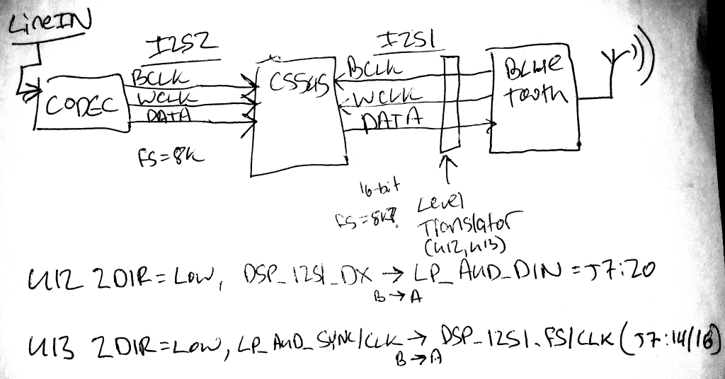
    Does your system look like the below drawing?

    The default direction of the U12, U13 level shifters requires the C5545 I2S1 to be the I2S slave (your Bluetooth device on J7 header is the clock/FS master):

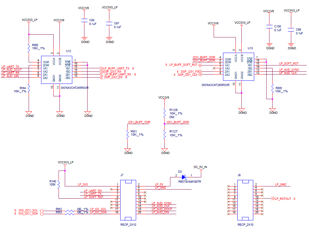
    U12 2DIR = Low, DSP_I2S1_DX --> LP_AUD_DIN = J7:20 (B --> A)

    U13 2DIR = Low, J7:14/16 = LP_AUD_SYNC/CLK --> DSP_I2S1_FS/CLK (B --> A)

    Can you confirm that VCC is provided to J7:1? 1.8V or 3.3V is fine - whichever the Bluetooth IO voltage is. This voltage is required and can be supplied from TP3 for 3.3V or TP4 for 1.8V (with a wire from TP to J7:1)

    Is your AIC3206 configured as the Master - drives BCLK and FS? I2C register writes control this.

    Is I2S2 configured as a Slave? I2SSCTRL:MODE bit = 0 for slave.

    You say the bluetooth is configured as the Master - drives BCLK and FS, right?

    Is I2S1 configured as a Slave? I2SSCTRL:MODE bit = 0 for slave.

    Is the codec configured to transmit Mono or Stereo? Each channel should be 16-bit.

    So if Mono, 16-bit with FS = 8000Hz, then BCLK should be 128000Hz. Can you confirm it is?

    BCLK rate is doubled for stereo. Can your Bluetooth device input and transmit stereo?

    The Bluetooth can be configured to provide the same FS (or WS) = 8k and BCLK = 128k. Saves any sample rate conversion in the DSP software.

    FS (WS) equals the sampling frequency (samples per second). How big the words are (16/20/24/32) and mono/stereo determine the BCLK frequency needed.

    Make sure the format of the FS is the same between codec and I2S2(I2S or DSP), and also Bluetooth and I2S1.

    Make sure that the delay from FS to data is configured the same (0-bit, 1-bit, 2-bit)

    Check CLK and FS polarity also.

    Keep I2S loopback bit disabled (this is for internal loopback, not external)

    Hope this helps,
    Mark

  • Mark,

    thanks for the reply.

    1) your picture and text says i should use Din, are you sure? isn't it Dout? because i need the audio from dsp to be transmitted to bluetooth.

    2)your picture says bclk and wclk from bluetooth to dsp j7 header pins. I've sck and ws pins on bluetooth and they should be connected to exactly what pins on j7 header? lp_aud_clk and lp_aud_sync respectively?

    3) yes i'm using 3.3v as my bluetooth is 3.3v. i'm using the t3 hole on boosterpack

    4)by default aic3206 is master and i2s output is slave i guess. i didn't change anything.

    5)do i've to make aic3206 also slave since my bluetooth is giving bclk and ws to dsp?

    6) i'm assuming its stereo as it rights data to left and right channels in my code and it is 16 bits

    7) for stereo bclk of bluetooth should be 16 or 20 or 24 or 32?

    8) yes ws of bluetooth is set to 8k

    9) i'm not sure how to do following  in my code, please can you be more precise

    // Make sure the format of the FS is the same between codec and I2S2(I2S or DSP), and also Bluetooth and I2S1.

    Make sure that the delay from FS to data is configured the same (0-bit, 1-bit, 2-bit)

    Keep I2S loopback bit disabled (this is for internal loopback, not external) //

  • Hi V Pot,

    Some answers to your questions. Let me know if this is the level of detail you are looking for.

    1) your picture and text says i should use Din, are you sure? isn't it Dout? because i need the audio from dsp to be transmitted to bluetooth.

    You need audio from dsp to be transmitted to bluetooth.
    LP_AUD_DIN is relative to the LaunchPad - DIN for the LaunchPad, Dout from the DSP
    Look at U12 level translator to see that LP_AUD_DIN connects to DSP_I2S1_DX (I2S data output)

    2)your picture says bclk and wclk from bluetooth to dsp j7 header pins. I've sck and ws pins on bluetooth and they should be connected to exactly what pins on j7 header? lp_aud_clk and lp_aud_sync respectively?
    Is SCK the same as BCLK? Is it 16x or 32x the frequency of ws? SCK could also be the system clock (called MCLK on our codecs) that is 12.288MHz or so. This gets divided down internally to generate a BCLK in the range 128k to 1.536MHz
    Is ws a clock that matches the sampling rate 8k or a strobe signal that pulses at an frequency of 8k? I2S can support either clock (I2S mode) or pulse (DSP mode)
    All naming issues I expect.
    J7 pin 14 = LP_AUD_SYNC = frame sync = FS = WS
    J7 pin 16 = LP_AUD_CLK = bit clock = BCLK = SCK (I hope)
    J7 pin 18 = LP_AUD_DOUT = output from launchpad - input to DSP
    J7 pin 20 = LP_AUD_DIN = input to launchpad - output from DSP

    3) yes i'm using 3.3v as my bluetooth is 3.3v. i'm using the t3 hole on boosterpack
    Great. Are you also supplying 3.3V to the bluetooth from the J7 header? It would be ideal if the 3.3V on the bluetooth is the same as the 3.3V on the BoosterPack level translators. Sometimes they can be off by a tenths of a volt or so.

    4)by default aic3206 is master and i2s output is slave i guess. i didn't change anything.
    Your program will perform several I2C writes to the AIC3206 codec to configure it (functions called AIC3206_write()...)- check what is being written to Page 0 Reg 27.


    AIC3206 has a register to define it as master (source/output of the bit clock and frame sync)
    See 5.2.27 Page 0 / Register 27: Audio Interface Setting Register 1 - 0x00 / 0x1B in TLV320AIC3206 Application Reference Guide (SLAA463B)
    Bit 3 BCLK Direction Control:
    0: BCLK is input to the device
    1: BCLK is output from the device
    Bit 2 WCLK Direction Control
    0: WCLK is input to the device
    1: WCLK is output from the device

    C5545 I2S register
    I2S2 I2SSCTRL = addres 0x2A00 - you can set a breakpoint in your program after I2S is setup and read the register I2S2-->I2SSCTRL and read the bits.

    See 10.3.1 I2Sn Serializer Control Register (I2SSCTRL) in the TMS320C5545/35/34/33/32 Ultra-Low Power DSP Technical Reference Manual (SPRUH87)
    I2SSCTRL Bit 1 MODE:
    0 = Serializer is configured as a slave. I2Sn_CLK and I2Sn_FS pins are configured as inputs. The bit-clock and frame-synchronization signals are derived from an external source and are provided directly to the I2S synchronizer without being further divided.
    1 = Serializer is configured as a master. I2Sn_CLK and I2Sn_FS pins are configured as outputs and driven by the clock generators. The bit-clock and frame synchronization signals are derived from the internal CPU clock.

    5)do i've to make aic3206 also slave since my bluetooth is giving bclk and ws to dsp?
    If you could connect the I2S BCLK and WCLK from the bluetooth to both I2S1, I2S2 (which is connected to the codec), then you could have one master (bluetooth) and 3 slaves (I2S1, I2S2, and CODEC). However, I the boosterpack is not setup that way. So instead you will have 2 masters and 2 slaves. AIC3204 is the I2S2 Master, C5545 I2S2 is the slave (recommended). Bluetooth is the I2S1 master, C5545 I2S1 is the slave recommended.
    Now when the AIC3206 generates 8k FS and 256k BCLK, it wont exactly match the Bluetooth 8k FS and 256k BCLK. When these frequencies drift apart over time, they will get out of sync, you will drop a sample, and hear a glitch or some artifact. Thats one reason to have one master and three slaves. DSPs can also run software to handle this - an Asynchronous Sample Rate Converter can seamlessly bridge these two slightly different clock rates.

    6) i'm assuming its stereo as it rights data to left and right channels in my code and it is 16 bits
    Stereo is typical. So the BCLK should = 2x16xFS = 2x16x8000 = 256000Hz. you will have a left 16-bit sample and a right 16-bit sample to process and transmit to the bluetooth.

    7) for stereo bclk of bluetooth should be 16 or 20 or 24 or 32?
    Hmmm, I'd have to see the bluetooth device documentation. Is it referring to each word(channel) or referring to the number of bits per frame? 2 channels x 16-bits per word per frame would be the same as 32-bits per frame.

    8) yes ws of bluetooth is set to 8k
    Ok

    9) i'm not sure how to do following in my code, please can you be more precise

    For the AIC3206, there will be a section of several AIC3206_write commands (uses I2C to write to registers on the AIC3206):
    AIC3206_write( 27, 0x0d ); // BCLK and WCLK are set as o/p; AIC3206(Master)

    The same I2SSCTRL has bits that define...
    - format (bit 0, set to 0 for I2S/left justified (clock) or 1 to DSP format (pulse)0
    - data delay (bit 8, set to 0 for 1-bit delay or 1 for 2-bit delay)
    - loopback (bit 11, set to 0 for normal)

    In the C5545 diagnostic source files (c55xx_diagnostics\board\diag), I2S configuration section is abstracted to be more human readable.
    Search for initialise_i2s_interface() and modify the parameters in the below format...
    hwConfig.dataType = I2S_STEREO_ENABLE;
    hwConfig.loopBackMode = I2S_LOOPBACK_DISABLE;
    hwConfig.fsPol = I2S_FSPOL_LOW;
    hwConfig.clkPol = I2S_RISING_EDGE;
    hwConfig.datadelay = I2S_DATADELAY_ONEBIT;
    hwConfig.datapack = I2S_DATAPACK_ENABLE;
    hwConfig.signext = I2S_SIGNEXT_DISABLE;
    hwConfig.wordLen = I2S_WORDLEN_32;
    hwConfig.i2sMode = I2S_SLAVE;
    hwConfig.FError = I2S_FSERROR_ENABLE;
    hwConfig.OuError = I2S_OUERROR_ENABLE;

    // Make sure the format of the FS is the same between codec and I2S2(I2S or DSP), and also Bluetooth and I2S1.

    Make sure that the delay from FS to data is configured the same (0-bit, 1-bit, 2-bit)

    Keep I2S loopback bit disabled (this is for internal loopback, not external) //

    Hope this helps,
    Mark
  • I would like make an addition to my above reply.

    - when i do the loopback, i want to transmit the i2s audio output to Bluetooth and also be able to listen it in my headphones connected to the headphone jack of booster pack

  • Mark,
    Thanks that’s very detailed reply. Please take a look at the Bluetooth doc below. Paragraph 6.67 example for clock calculation.
    www.silabs.com/.../UG218.pdf

    1) also with your procedure will be able to transmit data to Bluetooth and also listen on headphones from headphones jack on booster pack?

    2) 1master 3 slaves case is not possible with booster pack right? If I’m wrong how can i make Bluetooth master and all 3 components of booster pack slaves?

    3) Bluetooth module provides only bclk and it allows 8k or 16 k hz for ws.
  • Hi V Pot,

    V Pot said:
    1) also with your procedure will be able to transmit data to Bluetooth and also listen on headphones from headphones jack on booster pack?

    Yes, you can transmit the same audio data to DSP_I2S1_DX (LP_AUD_DIN to bluetooth) and to DSP_I2S2_DX (to AIC3206 DIN)

    V Pot said:
    2) 1master 3 slaves case is not possible with booster pack right? If I’m wrong how can i make Bluetooth master and all 3 components of booster pack slaves?

    1 master 3 slaves is not supported on the C5545 BoosterPack.

    It could be possible if you solder a wire from LP_AUD_CLK from JP7:16 to I2S2_CLK at R42 and LP_AUD_SYNC from JP7:14 to I2S2_FS at R43, but this would require your bluetooth device connected to J7 to work at 1.8V.

    To keep the 3.3V device at J7, you would have to solder to U13 pins 8 and 9, which are probably too small and too close together to achieve. But not impossible!

    V Pot said:
    3) Bluetooth module provides only bclk and it allows 8k or 16 k hz for ws.

    BCLK calculations are the same as mine: "The BCLK for CVSD should then be between 256 kHz (8kHz*2*16 ) and 512 kHz (8kHz*2*32) and for WBS/MSBC between 512 kHz (16kHz*2*16) and 1024 kHz (16kHz*2*32)." I'm not sure about the 16kHz*2*32 case though.

    Notes about usage of the I2S interface on page 146 make it seem like the bluetooth device must be a I2S slave.

    C5545 I2S1 would have to provide clocks and you'd have to change the direction of the U13 level shifter by desoldering R127 and soldering it onto the pads for R126.

    This document is a USER GUIDE AND API REFERENCE. Do you have a part number or datasheet to confirm?

  • Hey mark,

    1) probably I’ll make 1master 3slaves when i do my pcb for now i would like to try the case where aic3206 provides the i2s2 clock to dsp and wt32i (Bluetooth module) provides the bclk clock for i2s1 of dsp.

    2) no wt32i can provide bclk clock for i2s interface. It has a master clock generator inside it. To be more clear look at the following dev kit schematics where wt32i is providing clock yo an external ti audio codec on dev kit . I tested the dev kit by giving input the external codec and it transmits audio through i2s perfectly to wt32i. Please look at figure 8 in doc below where wt32i provides clock.

    3) here is the datasheet

    4) so from the clock calculations. Like i said my sample rate of audio is 8khz. And also aic3206 transmitting 16 bit data. So should i make the wt32i 16bit as well?

  • V Pot,

    Yes - I would match the I2S BCLK and WS rates on Codec and Bluetooth to make processing easy. Use an oscilloscope to confirm the clocks.

    Regards,
    Mark
  • mark,

    I see that in one of your above replies you mentioned to make sure that both bluetooth and dsp i2s are from same 3.3v. I'm using the bluettoth dev kit dkwt32i, it has options to powerup from usb, or a battery. i've to see on the board if i can give power input from dsp pins... if not can i give the 3.3v input to run the dsp and still be able to connect to laptop in debug mode and run the code composer to run the loopback test?

  • If you power both C5545 Boosterpack and the Bluetooth, then you should connect the 3.3V from the Bluetooth to J7 pin 1 (VCC3V3_LP) to give the level shifter a reference to level shift from 1.8V.

    The BoosterPack operates from 5V (1.8V is generated from 5V on the board). If you want to power the C5545 BoosterPack from some other board, you need to provide 5V to J7 pin 2 (DC_5V_IN). We placed diodes on the board to allow 5V to come from J7 pin 2 or either of the two USB ports.

    Yes, you can connect to a laptop and debug the board pretty much under all powering scenarios.

    Regards,
    Mark
  • Mark,

    Okie. So by connecting Bluetooth 3v3 to j7 3v3, i no more require to connect tp3 hole to j7 3.3v pin right?
  • V Pot,

    That's correct. J7 pin 1 LP_3V3 only supplies a reference to the level shifter. Nothing else.

    Regards,
    Mark
  • hi mike,

    I followed your instructions and i was successful partly. I was able to record the data transmitted from dsp to bluetooth using hfp profile on a mobile phone. but it is unstable, meaning sometimes it transmits sometimes it doesn't transmit anything. I made sure the refrence 3.3v, data, fs, bclk wires are all intact. still I don't undertsnad the underlying reason. please advise, thanks.
  • Hi V Pot,

    Cool.

    Do you have a scope to probe the I2S signals? They might reveal the issue or at least isolate the issue to the codec, C55xx, or bluetooth. For example if the I2S clocks and data look fine from the codec, it lets us know if the codec is transmitting data correctly.

    Maybe there is also something occurring on the I2C bus that is stopping the codec.

    Or it might be the software inside the C55xx. Try to isolate the issue. Maybe you could try writing dummy I2S traffic like a sine wave from the C55xx to the Bluetooth.

    Are you using I2S interrupts or DMA? You could add software counters inside the ISRs to compare the rates of each interrupt. I would expect the RX interrupts from one I2S port would match the TX interrupts for the other I2S port.

    Hope this helps,
    Mark

  • Mike.

    Thanks for the reply. What you said is little too technical for me, but I’ll try to understand and work on it.

    1) i can try scoping it.

    2)what do you mean by happening at I2c bus? You mean the i2s signal?

    3) what interrupts are you talking about? In Bluetooth or dsp?

    4) I’m using ccs to run the loopback example on booster pack which is connected to Bluetooth. There is no software as such inside booster pack

  • Mike,

    I would require to send the filtered dsp data to some sitara based processor as well for feeding it to some machine learning algorithm. As both i2s1 and i2s2 are being used for codec and bluetooth transmission device. How else can i send data to a micro processor as well?  Here is the processor we would like to use with the c5545 dsp

    if not i2s, what other options we got and how to implement them. Thanks in advance

  • Hey mark,

    Anything yet with the above concerns?

  • Hi V Pot,

    Use UART to communicate with the micro processor.

    It is very common to use UART to communicate between processors and the UART pins can be routed to the launchpad header of the C5545 BoosterPack.

    We used UART to communicate with the MSP430 with this other C55 Audio Capacitive Touch BoosterPack, but due to the software having MP3 encode, we could not release the source for it...

    http://processors.wiki.ti.com/index.php/Audio_Capacitive_Touch_BoosterPack_C5535_Software 

    http://processors.wiki.ti.com/index.php/Audio_Capacitive_Touch_BoosterPack_MSP430_Software

    http://processors.wiki.ti.com/index.php/Low-level_UART_Virtual_Register_Control_Protocol

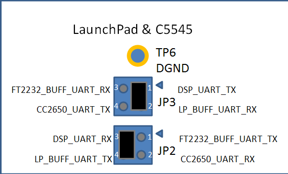
    Set these jumpers on C5545 BoosterPack to bring UART to the LaunchPad header.

    The Chip Support Library has UART examples: ti.com/tool/SPRC133

    Regards,
    Mark

  • Mark.
    So you confirming that we can transmit dsp audio from c5545 to above mentioned octavo ti based processor using uart interface?

    May i know in your above application the data that has been transmitted was in pcm format or mp3 format. Just wondering in what format would my processor receive the data in?
  • Oh sorry. We did not transfer audio via UART - just data and commands at a much slower baud rate.

    In theory the UART baud rate can run fast enough, but I have a hunch that it wouldn't be as simple as cranking it up and sending audio over the serial port.

    On the C5545, UART is pin muxed with I2S3, BUT the UART_CTS/ I2S3_FS goes to the SD card slot instead of the LaunchPad header.

    I2S3 might still be your best bet if you are willing to solder a wire to J3 pin 9 or R119... The other I2S3 / UART signals go to the launchpad header (through level shifter).

    Regards,
    Mark

  • Mark,

    1)Anyways we gonna make a pcb with just c5545 , aic3206. So you are confirming that  c5545 dsp has a i2s3 to use for transmitting to the micro processor?

    2) I haven’t decided weather I’m gonna add a touch screen led to dsp or the microprocessor. But i choose to do it from c5545dsp what would be my best bet to do it?.

    3) if i add a touch screen to the dsp. I need to write my iterrupts related to the touch screen on dsp. So will that affects the performance of dsp? As I’m gonna paralleling running my dsp filters on it and i expect it to be real time no latency.

    4) can i use tp3 or tp1 as 3v3 or 1v8 power supply to run my external analog circuit? If not is there a way I could supply a 1v8 to external circuit. What pin should i use for ground rail?

  • Mark,

    Any solutions to my above questions yet?
  • Mark,

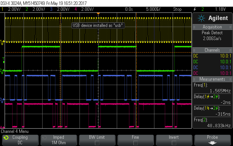
    1)I've scoped the boosterpack i2s output and i'm receiving nothing. I scoped DIN, I2S CLK, I2S FSYNC. i don't see a reading.

    2)i scoped the bluetooth and its working fine.

    3) i assume the problem is with the aic3206 settings or something in the boosterpack. TI codec expert Diego, said that in my settings I'm using BCLK N divider value 8 and he suggested me to use 48 to make i2s work. and still no luck.

    following is the complete code of the loopback test with aic3206 settings, i'm using in css.

    NOTE:- don't follow the comments in the code, they mean nothing. just look the register number and value associated and debug.

    /*
     * Copyright (c) 2016, Texas Instruments Incorporated
     * All rights reserved.
     *
     * Redistribution and use in source and binary forms, with or without
     * modification, are permitted provided that the following conditions
     * are met:
     *
     * *  Redistributions of source code must retain the above copyright
     *    notice, this list of conditions and the following disclaimer.
     *
     * *  Redistributions in binary form must reproduce the above copyright
     *    notice, this list of conditions and the following disclaimer in the
     *    documentation and/or other materials provided with the distribution.
     *
     * *  Neither the name of Texas Instruments Incorporated nor the names of
     *    its contributors may be used to endorse or promote products derived
     *    from this software without specific prior written permission.
     *
     * THIS SOFTWARE IS PROVIDED BY THE COPYRIGHT HOLDERS AND CONTRIBUTORS "AS IS"
     * AND ANY EXPRESS OR IMPLIED WARRANTIES, INCLUDING, BUT NOT LIMITED TO,
     * THE IMPLIED WARRANTIES OF MERCHANTABILITY AND FITNESS FOR A PARTICULAR
     * PURPOSE ARE DISCLAIMED. IN NO EVENT SHALL THE COPYRIGHT OWNER OR
     * CONTRIBUTORS BE LIABLE FOR ANY DIRECT, INDIRECT, INCIDENTAL, SPECIAL,
     * EXEMPLARY, OR CONSEQUENTIAL DAMAGES (INCLUDING, BUT NOT LIMITED TO,
     * PROCUREMENT OF SUBSTITUTE GOODS OR SERVICES; LOSS OF USE, DATA, OR PROFITS;
     * OR BUSINESS INTERRUPTION) HOWEVER CAUSED AND ON ANY THEORY OF LIABILITY,
     * WHETHER IN CONTRACT, STRICT LIABILITY, OR TORT (INCLUDING NEGLIGENCE OR
     * OTHERWISE) ARISING IN ANY WAY OUT OF THE USE OF THIS SOFTWARE,
     * EVEN IF ADVISED OF THE POSSIBILITY OF SUCH DAMAGE.
     *
     */
    
    /*! \file audio_line_in_loopback_test.c
    *
    *   \brief Functions that configure the audio codec regsiters for the audio
    *          line in loopback operation.
    *
    */
    
    #include "audio_line_in_loopback_test.h"
    #include "audio_common.h"
    #include "../../../build/boostC5545/audio_line_in_loopback_test/coeff"
    #include <math.h>
    extern TEST_STATUS AIC3206_loop_linein(void *testArgs);
    
    /**
     *
     * \brief This function configures all audio codec registers for
     *        line in loopback test
     *
     * \param    testArgs   [IN]   Test arguments
     *
     * \return
     * \n      TEST_PASS  - Test Passed
     * \n      TEST_FAIL  - Test Failed
     *
     */
    TEST_STATUS AIC3206_loop_linein(void *testArgs)
    {
    	    Int16 sec, msec;
    	    Int16 sample;
    	    Int16 data1, data2;
    	    Int16 output1,output2;
    
    	    /* Configure AIC3206 */
    	    AIC3206_write( 0,  0x00 );  // Select page 0
    	    AIC3206_write( 1,  0x01 );  // Reset codec
    	    C55x_delay_msec(1);  		// Wait 1ms after reset
    	    AIC3206_write( 0,  0x01 );  // Select page 1
    	    AIC3206_write( 1,  0x0a );  // Disable crude AVDD generation from DVDD
    	    AIC3206_write( 2,  0x01 );  // Enable Analog Blocks, use LDO power
    	    AIC3206_write( 123,0x05 );  // Force reference to power up in 40ms
    	    AIC3206_write( 124,0x06 );
    
    	    C55x_delay_msec(40); 		// Wait at least 40ms
    	    AIC3206_write( 0,  0x00 );  // Select page 0
    
    	    /* PLL and Clocks config and Power Up  */
    	    AIC3206_write( 27, 0x0d );  // BCLK and WCLK are set as o/p; AIC3206(Master)
    	    AIC3206_write( 28, 0x00 );  // Data ofset = 0
    	    AIC3206_write( 4,  0x03 );  // PLL setting: PLLCLK <- MCLK, CODEC_CLKIN <-PLL CLK
    	    AIC3206_write( 6,  0x07 );  // PLL setting: J=7
    	    AIC3206_write( 7,  0x06 );  // PLL setting: HI_BYTE(D=1680)
    	    AIC3206_write( 8,  0x90 );  // PLL setting: LO_BYTE(D=1680)
    	    AIC3206_write( 30, 0xB0 );  // For 32 bit clocks per frame in Master mode ONLY
    	                               	// BCLK=DAC_CLK/N =(12288000/8) = 1.536MHz = 32*fs
    	    AIC3206_write( 5,  0x91 );  // PLL setting: Power up PLL, P=1 and R=1
    		C55x_delay_msec(1); 		// Wait for PLL to come up
    		AIC3206_write( 13, 0x00 );  // Hi_Byte(DOSR) for DOSR = 128 decimal or 0x0080 DAC oversamppling
    		AIC3206_write( 14, 0x80 );  // Lo_Byte(DOSR) for DOSR = 128 decimal or 0x0080
    		AIC3206_write( 20, 0x80 );  // AOSR for AOSR = 128 decimal or 0x0080 for decimation filters 1 to 6
    		AIC3206_write( 11, 0x87 ); // Power up NDAC and set NDAC value to 7
    		AIC3206_write( 12, 0x8C ); // Power up MDAC and set MDAC value to 12
    		AIC3206_write( 18, 0x87 ); // Power up NADC and set NADC value to 7
    		AIC3206_write( 19, 0x8C ); // Power up MADC and set MADC value to 12
    
    
    	    /* DAC ROUTING and Power Up */
    	    AIC3206_write( 0,  0x01 );  // Select page 1
    	    AIC3206_write( 12, 0x08 );  // LDAC AFIR routed to HPL
    	    AIC3206_write( 13, 0x08 );  // RDAC AFIR routed to HPR
    	    AIC3206_write( 0,  0x00 );  // Select page 0
    	    AIC3206_write( 64, 0x02 );  // Left vol=right vol
    	    AIC3206_write( 65, 0x00 );  // Left DAC gain to 0dB VOL; Right tracks Left
    	    AIC3206_write( 63, 0xd4 );  // Power up left,right data paths and set channel
    	    AIC3206_write( 0,  0x01 );  // Select page 1
    	    AIC3206_write( 16, 0x03 );  // Unmute HPL , 0dB gain
    	    AIC3206_write( 17, 0x03 );  // Unmute HPR , 0dB gain
    	    AIC3206_write( 9 , 0x30 );  // Power up HPL,HPR
    	    C55x_delay_msec(1 );        // Wait 1 msec
    
    	    /* ADC ROUTING and Power Up */
    	    	    	    AIC3206_write( 0,  0x01 );  // Select page 1
    	    	    	    AIC3206_write( 52, 0x40 );  // STEREO 1 Jack
    	    	    	                               	// IN2_L to LADC_P through 40 kohm
    	    	    	    AIC3206_write( 55, 0x40 );  // IN2_R to RADC_P through 40 kohmm
    	    	    	    AIC3206_write( 54, 0x40 );  // CM_1 (common mode) to LADC_M through 40 kohm
    	    	    	    AIC3206_write( 57, 0x40 );  // CM_1 (common mode) to RADC_M through 40 kohm
    	    	    	    AIC3206_write( 59, 0x00 );  // MIC_PGA_L unmute
    	    	    	    AIC3206_write( 60, 0x00 );  // MIC_PGA_R unmute
    	    	    	    AIC3206_write( 61, 0x00 );
    	    	    		AIC3206_write( 51, 0x00 );      // SetMICBIAS
    
    	    	    	    AIC3206_write( 0,  0x00 );  // Select page 0
    	    	    	    AIC3206_write( 81, 0xc0 );  // Powerup Left and Right ADC
    	    	    	    AIC3206_write( 82, 0x00 );  // Unmute Left and Right ADc
    	    	    	    AIC3206_write( 83, 0x00 );  // Unmute Left and Right ADC
    	    				AIC3206_write( 84, 0x00 );  // Unmute Left and Right ADC
    	    				//AIC3206_write( 86, 0x80 );  // L-AGC configuration
    	    				//AIC3206_write( 94, 0x80 );  // R-AGC configuration
    
    	    C55x_delay_msec(1 );        // Wait 1 msec
    
    	    /* Initialize I2S */
    	    initialise_i2s_interface();
    	    gpio_interrupt_initiliastion();
    
    	    /*Circular Buffer FIR Implementation*/
    	    Int16 coeff1[135];
    
    	    int N=135;
    	    int i,n;
    	    int index1=0;
    	    int index2=N;
    	    Int16 x[2*135];
    	    Int16 z[2*135];
    	    long y1new,y2new;
    	    int k=0;
    	    I2S_writeLeft(0);
    		I2S_writeRight(0);
    		/*for(n=0;n<N;n++){
    			coeff1[n]=round(coeff[n]*32);
    		}*/
    	    for ( sec = 0 ; sec < 600 ; sec++ )
    	    	    {
    	    	        for ( msec = 0 ; msec < 1000 ; msec++ )
    	    	        {
    	    	            for ( sample = 0 ; sample < 8 ; sample++ )
    	    	            {
    	    	                // Read 16-bit left channel Data
    	    	            	I2S_readLeft(&data1);
    
    	    	                // Read 16-bit right channel Data
    	    	                I2S_readRight(&data2);
    
    
    	    	                // As a new sample is received put it in two places
    	    	                x[index1] = data1;
    	    	                x[index2] = data1;
    	    	                z[index1] = data2;
    	    	                z[index2] = data2;
    	    	                y1new=0;
    	    	                y2new=0;
    	    	                for(i=0;i<N;i++){
    	    	                y1new = y1new + (long)coeff[i]*x[index2-i];
    	    	                y2new = y2new + (long)coeff[i]*z[index2-i];
    	    	                }
    
    	    	                index1 = (index1+1)%N;
    	    	                index2 = index1+N;
    
                                output1=y1new>>15;
                                output2=y2new>>15;
    
    
    	    	                // Write 16-bit left channel Data
    	    	                I2S_writeLeft(data1);
    
    	    	                // Write 16-bit right channel Data
    	    	                I2S_writeRight(data2);
    	    	            }
    	    	            if(sw3Pressed == TRUE)
    	    	            {
    	    	            	break;
    	    	            }
    
    	    	        }
    	                if(sw3Pressed == TRUE)
    	                {
    	                	break;
    	                }
    
    	    	    }
    	    /* Play Loop for 5 seconds */
    
    	  /*  for ( sec = 0 ; sec < 500 ; sec++ )
    	    {
    	        for ( msec = 0 ; msec < 1000 ; msec++ )
    	        {
    	            for ( sample = 0 ; sample < 16 ; sample++ )
    	            {
    	                 Read 16-bit left channel Data
    	            	I2S_readLeft(&data1);
    	                 Read 16-bit right channel Data
    	                I2S_readRight(&data2);
    
    	                 Write 16-bit left channel Data
    	                I2S_writeLeft(data1);
    
    	                 Write 16-bit right channel Data
    	                I2S_writeRight(data2);
    	            }
    	            if(sw3Pressed == TRUE)
    	            {
    	            	break;
    	            }
    
    	        }
                if(sw3Pressed == TRUE)
                {
                	break;
                }
    
    	    }*/
    	    I2S_close(hI2s);    // Disble I2S
    	    AIC3206_write( 1, 0x01 );  // Reset codec
    
    	    return 0;
    }
    
    /**
     *
     * \brief This function used to initialise i2c interface and run
     *        audio line in loopback test
     *
     * \param    testArgs   [IN]   Test arguments
     *
     * \return
     * \n      TEST_PASS  - Test Passed
     * \n      TEST_FAIL  - Test Failed
     *
     */
    static TEST_STATUS run_audio_line_in_loopback_test(void *testArgs)
    {
    	 Int16 retVal;
    	 Uint8  c = 0;
    
    	 /* Enable clocks to all peripherals */
    	 CSL_SYSCTRL_REGS->PCGCR1 = 0x0000;
    	 CSL_SYSCTRL_REGS->PCGCR2 = 0x0000;
    
    	 retVal =  SYS_setEBSR(CSL_EBSR_FIELD_PPMODE,
    			               CSL_EBSR_PPMODE_1);    // Configure Parallel Port for I2S2
    	 retVal |= SYS_setEBSR(CSL_EBSR_FIELD_SP1MODE,
    	                          CSL_EBSR_SP1MODE_1);  // Serial Port mode 1 (I2S1 and GP[11:10]).
    
    	 retVal = initialise_i2c_interface(testArgs);
    	 if(retVal != 0)
    	 {
    		 C55x_msgWrite("I2C initialisation failed\n\r");
    		 return (TEST_FAIL);
    	 }
    
    	 C55x_msgWrite( "Test Receives audio samples from LINE IN and output the same\n\r"
    			        "on HEADPHONE port\n\n\r");
    
    	 C55x_msgWrite("Connect headset to the HEADPHONE port of the BoosterPack\n\n\r");
    	 C55x_msgWrite("Connect a LINE-IN cable between the audio port of the\n\r"
    			       "Test PC and LINE IN of the BoosterPack\n\n\r");
    
    	 C55x_msgWrite("Play any audio file from the Test PC and Check \n\r"
    			       "Audio from the headset connected to BoosterPack\n\n\r");
    
    	 retVal = AIC3206_loop_linein(testArgs);
    	 if(retVal != 0)
    	 {
    		 return (TEST_FAIL);
    	 }
    
    #ifdef USE_USER_INPUT
    
    	 C55x_msgWrite("Press Y/y if the Audio stream from LINE IN is\n\r"
    			       "observed at the headset connected to HEADPHONE port,\n\r"
    			       "any other key for failure:\n\r");
    
    	 C55x_msgRead(&c, 1);
    	 if((c != 'y') && (c != 'Y'))
    	 {
    		 C55x_msgWrite("Audio Loopback from LINE IN to the HEADPHONE port\n\r"
    				       "is not proper\n\r");
    		 return (TEST_FAIL);
    	 }
    #endif
    
    	 return (TEST_PASS);
    
    }
    
    /**
     *
     * \brief This function performs audio line in loopback test
     *
     * \param    testArgs   [IN]   Test arguments
     *
     * \return
     * \n      TEST_PASS  - Test Passed
     * \n      TEST_FAIL  - Test Failed
     *
     */
     TEST_STATUS audioLineInLoopbackTest(void *testArgs)
     {
         TEST_STATUS testStatus;
    
         C55x_msgWrite("\n*******************************************\n\r");
         C55x_msgWrite(  "        AUDIO LINE IN LOOPBACK TEST    \n\r");
         C55x_msgWrite(  "*******************************************\n\r");
    
         testStatus = run_audio_line_in_loopback_test(testArgs);
         if(testStatus != TEST_PASS)
         {
         	C55x_msgWrite("\nAudio LINE IN Loopback Test Failed!\n\r");
         	return (TEST_FAIL);
         }
         else
         {
         	C55x_msgWrite("\nAudio LINE IN Loopback Test Passed!\n\r");
         }
    
         C55x_msgWrite("\nAudio LINE IN Loopback Test Completed!!\n\r");
    
         return testStatus;
    
     }


    Please provide a solution. I've been hanging around these forums for a while and still my issue hasn't been resolved


  • continuation to above loopback test code... functions used in the above loopback test settings for aic3206 are defined in audio_common.c module and i'm attaching the code in the module below. it also consists the I2C configuration. please take a look and let me know if i need to change any of those settngs.

    /*
     * Copyright (c) 2016, Texas Instruments Incorporated
     * All rights reserved.
     *
     * Redistribution and use in source and binary forms, with or without
     * modification, are permitted provided that the following conditions
     * are met:
     *
     * *  Redistributions of source code must retain the above copyright
     *    notice, this list of conditions and the following disclaimer.
     *
     * *  Redistributions in binary form must reproduce the above copyright
     *    notice, this list of conditions and the following disclaimer in the
     *    documentation and/or other materials provided with the distribution.
     *
     * *  Neither the name of Texas Instruments Incorporated nor the names of
     *    its contributors may be used to endorse or promote products derived
     *    from this software without specific prior written permission.
     *
     * THIS SOFTWARE IS PROVIDED BY THE COPYRIGHT HOLDERS AND CONTRIBUTORS "AS IS"
     * AND ANY EXPRESS OR IMPLIED WARRANTIES, INCLUDING, BUT NOT LIMITED TO,
     * THE IMPLIED WARRANTIES OF MERCHANTABILITY AND FITNESS FOR A PARTICULAR
     * PURPOSE ARE DISCLAIMED. IN NO EVENT SHALL THE COPYRIGHT OWNER OR
     * CONTRIBUTORS BE LIABLE FOR ANY DIRECT, INDIRECT, INCIDENTAL, SPECIAL,
     * EXEMPLARY, OR CONSEQUENTIAL DAMAGES (INCLUDING, BUT NOT LIMITED TO,
     * PROCUREMENT OF SUBSTITUTE GOODS OR SERVICES; LOSS OF USE, DATA, OR PROFITS;
     * OR BUSINESS INTERRUPTION) HOWEVER CAUSED AND ON ANY THEORY OF LIABILITY,
     * WHETHER IN CONTRACT, STRICT LIABILITY, OR TORT (INCLUDING NEGLIGENCE OR
     * OTHERWISE) ARISING IN ANY WAY OUT OF THE USE OF THIS SOFTWARE,
     * EVEN IF ADVISED OF THE POSSIBILITY OF SUCH DAMAGE.
     *
     */
    
    /*! \file audio_common.c
    *
    *   \brief Functions for initializing i2c and i2s interfaces and read and
    *          operations using these intefaces.
    *
    */
    
    #include "audio_common.h"
    
    CSL_I2sHandle   hI2s = 0;
    volatile Uint16  sw3Pressed = 0;
    
    /**
     *  \brief  GPIO Interrupt Service Routine
     *
     *  \param testArgs   [IN]   Test arguments
     *
     *  \return none
     */
    interrupt void gpioISR(void)
    {
       	Int16 retVal;
    
    	IRQ_globalDisable();
    	/* Disable all the interrupts */
    	IRQ_disableAll();
    
        /* Check for GPIO Interrupt Flag Register */
    	if((1 == GPIO_statusBit(gpioHandle,CSL_GPIO_PIN13,&retVal)))
        {
            /* Clear GPIO Interrupt Flag Register */
            GPIO_clearInt(gpioHandle,CSL_GPIO_PIN13);
            sw3Pressed = 1;
        }
    
    	IRQ_clear(GPIO_EVENT);
    }
    
    TEST_STATUS gpio_interrupt_initiliastion(void)
    {
    
    	Int16 retVal;
    
    	CSL_GpioPinConfig    config;
    	volatile Uint32 	 loop;
    	sw3Pressed = 0;
    
    	/* Set Bus for GPIOs */
    	CSL_FINST(CSL_SYSCTRL_REGS->EBSR, SYS_EBSR_PPMODE, MODE1);
    
        /* Disable CPU interrupt */
        IRQ_globalDisable();
    
    	/* Clear any pending interrupts */
    	IRQ_clearAll();
    
    	/* Disable all the interrupts */
    	IRQ_disableAll();
    
        /* Initialize Interrupt Vector table */
        IRQ_setVecs((Uint32)(&VECSTART));
    
    	/* Open GPIO module */
        gpioHandle = GPIO_open(&GpioObj,&retVal);
        if((NULL == gpioHandle) || (CSL_SOK != retVal))
        {
            C55x_msgWrite("GPIO_open failed\n");
            return (TEST_FAIL);
        }
    
    	/* Reset the GPIO module */
        GPIO_reset(gpioHandle);
    
        for (loop=0; loop < 0x5F5E10; loop++){}
    
        C55x_msgWrite("Press SW3 on the BoosterPack for exiting from the test\n\n\r");
    
        /** test GPIO_config API to make PIN13 as i/p */
    	config.pinNum    = CSL_GPIO_PIN13;
        config.direction = CSL_GPIO_DIR_INPUT;
        config.trigger   = CSL_GPIO_TRIG_RISING_EDGE;
        retVal = GPIO_configBit(gpioHandle,&config);
    	if(CSL_SOK != retVal)
    	{
    		C55x_msgWrite("test failed - GPIO_configBit\n");
    	     return (TEST_FAIL);
    	}
    
    	/* Enable GPIO interrupts */
        retVal = GPIO_enableInt(gpioHandle,CSL_GPIO_PIN13);
    	if(CSL_SOK != retVal)
    	{
    		C55x_msgWrite("test failed- GPIO_enableInt\n");
    		return(retVal);
    	}
    
    	/* Clear any pending Interrupt */
        IRQ_clear(GPIO_EVENT);
    
        IRQ_plug(GPIO_EVENT,&gpioISR);
    
         /* Enabling Interrupt */
        IRQ_enable(GPIO_EVENT);
        IRQ_globalEnable();
    
    	return (TEST_PASS);
    
    }
    
    /**
     *
     * \brief This function used to Enable and initalize the I2S module
     *
     * \param void
     *
     * \return
     * \n      TEST_PASS  - Test Passed
     * \n      TEST_FAIL  - Test Failed
     *
     */
    TEST_STATUS initialise_i2s_interface(void)
    {
    	I2S_Config      hwConfig;
    	Int16           result = 0;
    
    	/* Open the device with instance 0 */
    	hI2s = I2S_open(I2S_INSTANCE2, I2S_POLLED, I2S_CHAN_STEREO);
    
    	/* Set the value for the configure structure */
    	hwConfig.dataType           = I2S_STEREO_ENABLE;
    	hwConfig.loopBackMode       = I2S_LOOPBACK_DISABLE;
    	hwConfig.fsPol              = I2S_FSPOL_LOW;
    	hwConfig.clkPol             = I2S_RISING_EDGE;
    	hwConfig.datadelay          = I2S_DATADELAY_ONEBIT;
    	hwConfig.datapack           = I2S_DATAPACK_ENABLE;
    	hwConfig.signext            = I2S_SIGNEXT_DISABLE;
    	hwConfig.wordLen            = I2S_WORDLEN_32;
    	hwConfig.i2sMode            = I2S_SLAVE;
    	hwConfig.FError             = I2S_FSERROR_ENABLE;
    	hwConfig.OuError            = I2S_OUERROR_ENABLE;
    
    	/* Configure hardware registers */
    	result += I2S_setup(hI2s, &hwConfig);
    	result += I2S_transEnable(hI2s, TRUE);
    
    	return result;
    
    }
    
    /**
     *
     * \brief This function Reads incoming I2S left channel word and writes it
     *      to the location of "data".
     *
     * \param   *data - Pointer to location if I2S data destination
     *
     * \return void
     *
     */
    void I2S_readLeft(Int16* data)
    {
        ioport  CSL_I2sRegs   *regs;
    
        regs = hI2s->hwRegs;
        while((0x08 & regs->I2SINTFL) == 0);  // Wait for receive interrupt to be pending
        *data = regs->I2SRXLT1 ;              // 16 bit left channel receive audio data
    }
    
    /**
     *
     * \brief This function used to Writes I2S left channel word
     *
     * \param  data -I2S left data
     *
     * \return void
     *
     */
    void I2S_writeLeft(Int16 data)
    {
        ioport  CSL_I2sRegs   *regs;
    
        regs = hI2s->hwRegs;
        while((CSL_I2S_I2SINTFL_XMITSTFL_MASK & regs->I2SINTFL) == 0);  // Wait for transmit interrupt to be pending
        regs->I2STXLT1 = (data) ;            // 16 bit left channel transmit audio data
    }
    
    /**
     *
     * \brief This function Reads incoming I2S right channel word and writes it
     *      to the location of "data".
     *
     * \param   *data - Pointer to location if I2S data destination
     *
     * \return void
     *
     */
    void I2S_readRight(Int16* data)
    {
        ioport  CSL_I2sRegs   *regs;
    
        regs = hI2s->hwRegs;
    //  while((0x08 & regs->I2SINTFL) == 0);  // Wait for receive interrupt to be pending
        *data = regs->I2SRXRT1 ;              // 16 bit left channel receive audio data
    }
    
    /**
     *
     * \brief This function used to Writes I2S right channel word
     *
     * \param  data -I2S right data
     *
     * \return void
     *
     */
    void I2S_writeRight(Int16 data)
    {
        ioport  CSL_I2sRegs   *regs;
    
        regs = hI2s->hwRegs;
    //  while((CSL_I2S_I2SINTFL_XMITSTFL_MASK & regs->I2SINTFL) == 0);  // Wait for transmit interrupt to be pending
        regs->I2STXRT1 = (data) ;              // 16 bit left channel transmit audio data
    }
    
    /**
     *
     * \brief This function used to Enable and initalize the I2C module
     *		   The I2C clk is set to run at 100 KHz
     *
     * \param    testArgs   [IN]   Test arguments
     *
     * \return
     * \n      TEST_PASS  - Test Passed
     * \n      TEST_FAIL  - Test Failed
     *
     */
    TEST_STATUS initialise_i2c_interface(void *testArgs)
    {
    	CSL_Status         status;
    	CSL_I2cConfig         i2cConfig;
    
    	status = I2C_init(CSL_I2C0);
    
    	/* Configure I2C module for write */
    	i2cConfig.icoar  = CSL_I2C_ICOAR_DEFVAL;
    	i2cConfig.icimr  = CSL_I2C_ICIMR_DEFVAL;
    	i2cConfig.icclkl = 20;
    	i2cConfig.icclkh = 20;
    	i2cConfig.icsar  = CSL_I2C_ICSAR_DEFVAL;
    	i2cConfig.icmdr  = CSL_I2C_ICMDR_WRITE_DEFVAL;
    	i2cConfig.icemdr = CSL_I2C_ICEMDR_DEFVAL;
    	i2cConfig.icpsc  = 20;
    
    	status |= I2C_config(&i2cConfig);
    
    	return 0;
    
    }
    
    /**
     *
     * \brief This function used to write into the audio codec registers
     *
     * \param testArgs  regnum - register number
     *                  regVal - register data
     *
     * \return
     * \n      TEST_PASS  - Test Passed
     * \n      TEST_FAIL  - Test Failed
     *
     */
    TEST_STATUS AIC3206_write(Uint16 regnum, Uint16 regval)
    {
    	Int16 retVal;
    	Uint16 startStop            = ((CSL_I2C_START) | (CSL_I2C_STOP));
    	Uint16 cmd[2];
        cmd[0] = regnum & 0x007F;       // 7-bit Device Register
        cmd[1] = regval;                // 8-bit Register Data
    
        C55x_delay_msec(3);
    
        /* I2C Write */
        retVal = I2C_write(cmd, 2, AIC3206_I2C_ADDR,
        		 TRUE, startStop, CSL_I2C_MAX_TIMEOUT);
         if(retVal != 0)
         {
        	C55x_msgWrite("I2C Write failed\n\r");
     		//return -1;
         }
    
         return (0);
    }
    

  • Hey mark,

    Did you get a chance to look into above two codes?

  • Hi mark ,

    I appreciate your help so far. But if you are busy can you forward the case to other ti expert who can resolve my issue. Because we are getting late with our project

  • Hi V Pot, 

    Sorry, I missed your responses.

    V Pot said:

    1)Anyways we gonna make a pcb with just c5545 , aic3206. So you are confirming that c5545 dsp has a i2s3 to use for transmitting to the micro processor?


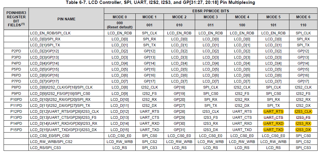
    Yes, the C5545 has an I2S3 that you can use to transmit audio to a microprocessor. Refer to Table 6-7 for I2S2 and I2S3. THen Table 6-8 and Table 6-9 for the I2S1 and I2S0 pin mux selections.

    V Pot said:

    2) I haven’t decided weather I’m gonna add a touch screen led to dsp or the microprocessor. But i choose to do it from c5545dsp what would be my best bet to do it?.

    It's probably better to add touchscreen to the microprocessor.
    If you add touchscreen to the C5545 DSP, you will have to use SPI or I2C for both display and touchscreen capture. This will limit its resolution and refresh rate.
    I'm not sure about touch screens, but you can find an OLED display that will work with SPI - we use this on the C5517 EVM (support.spectrumdigital.com/.../evm5517)
    OSD-2828GDEDF11 - https://www.osddisplays.com/

    There are software examples for this SPI display in the Spectrum Digital Target Content (support.spectrumdigital.com/.../evm5517_EVM_BSL_revf.zip)

    The Display on the C5545 BoosterPack uses I2C and its software can be found in the BoosterPack software diagnostic files.

    Most touchscreens are I2C based. There are also touchscreens that use the SAR ADC on the C55x DSP. See 11.2.7 Touch Screen Digitizing in the TRM.
    The one catch with using the C5545 to do this ADC touchscreen method, is that it does not have the GPAIN0 pin like the C5535, C5515, C5505 family members do.

    Keep in mind that the C5545 has 100MHz maximum clock rate, so everything must run in realtime at this clock rate (audio processing, etc).

    V Pot said:

    3) if i add a touch screen to the dsp. I need to write my iterrupts related to the touch screen on dsp. So will that affects the performance of dsp? As I’m gonna paralleling running my dsp filters on it and i expect it to be real time no latency.


    You can profile your software with CCS and find out how many cycles each function (filtering, ISRs) take. THen you can work backwards from your periodic realtime deadlines to see how many cycles are remaining unused. Your real time deadlines will be dictated by the audio clock rates - 16kHz = 62.5uS to get audio data in, process it, and get it back out. At 100MHz, that is 6250 cycles. (62.5E-6 / 10E-9).

    V Pot said:

    4) can i use tp3 or tp1 as 3v3 or 1v8 power supply to run my external analog circuit? If not is there a way I could supply a 1v8 to external circuit. What pin should i use for ground rail?

    You can use either of these supplies as long as the current maximum out of each supply is not exceeded.

    Refer to the datasheets for TPS62161 and TPS62162 - they each say they can supply upto 1A. That is quite a lot. Instantaneous current spikes should be supplied by bulk capacitors located near the MCU - 10uF caps to source current spikes which are common on digital processors. The noise may increase on these supplies with another MCU being supplied by them.

    Make sure to connect GND between boards so they are at the same reference. All the GND pins except for the audio jacks all shorted to the GND plane - I'd say J8 pin 2 or J7 pin 4.

    V Pot said:

    1)I've scoped the boosterpack i2s output and i'm receiving nothing. I scoped DIN, I2S CLK, I2S FSYNC. i don't see a reading.


    Are you probing I2S3 signals? Where are you probing DIN, I2S CLK, I2S FSYNC? Is there a codec connected to I2S3 / UART? Is the codec providing clocks to I2S3 or is the C5545 supposed to drive the clocks?

    Did you set JP2 and JP3 accordingly?
    Did you solder a wire to J3 pin 9 or R119 to connect to I2S3_FS?
    Did you solder a wire to LED3 signal R58 for to connect to I2S3_CLK?
    I think it will be easier to probe these signals with the C5545 as the I2S3 master (transmits) instead of the slave (receives clocks).
    Keep in mind that the IO voltage of the C5545 is 1.8V, and there is a level shifter for the UART_RX/TX signals (I2S3_RX/TX) that might allow them to go to 3.3V. There is no level shifter for the I2S3_FS and I2S3_CLK signals, so they must stay at 1.8V.
    When you make your own board, you can match the IO voltage or level shift all 4 signals.


    Studying your code a little bit...

    =-=-=-=-
    In AIC3206_loop_linein(), it looks like the codec is configured to output the clocks...
    AIC3206_write( 27, 0x0d ); // BCLK and WCLK are set as o/p; AIC3206(Master)

    =-=-=-=-
    initialise_i2s_interface() seems to initialize only I2S2. You need to also initialize I2S1 and I2S3, right? Copy and paste with 1 and 3 configured with modifications as needed.
    TEST_STATUS initialise_i2s_interface(void)
    {
    I2S_Config hwConfig;
    Int16 result = 0;

    /* Open the device with instance 0 */
    hI2s = I2S_open(I2S_INSTANCE2, I2S_POLLED, I2S_CHAN_STEREO);


    =-=-=-=-

    This software is polling the I2S receive registers - would be better to use interrupts, especially if you are servicing multiple I2S ports...
    But if the I2S are completely synchronized, it is possible to receive from one port with polling (and block everything else except interrupts while waiting for that reception), and then transmit to both ports at the same time. That transmission needs to occur well before the next receive (62.5us or 6250 cycles)...

    // Read 16-bit left channel Data
    I2S_readLeft(&data1);

    // Read 16-bit right channel Data
    I2S_readRight(&data2);

    =-=-=-=-
    The pin mux is configuring I2S3 to be UART - change PPMODE_1 to PPMODE_6 for I2S3...
    retVal = SYS_setEBSR(CSL_EBSR_FIELD_PPMODE, CSL_EBSR_PPMODE_1); // Configure Parallel Port for I2S2

    Hope this helps,
    Mark

  • Mark,

    Please look at my initial issue of this thread. I’m not talking about i2s3.

    I’m trying to transmit the i2s output from i2s pins on j7 header. I guess they are i2s1 . I asked about i2s3 for future implementation of microprocessor. First i need to finalize the boosterpack dsp.

    Please provide the code for initialize i2s for j7 pin headers.

    Also I don’t understand if i2s1 is not initialized how i transmitted once the data before and not now? Please refer to my previous replies where I mentioned i was successful for few times in transmitting the data
  • Continuation to above reply......

    Can you test my code on a boosterpack on your end and see if it works for you. You can do the changes you were talking, that way it would be faster to debug the issue. I stress the point again, i need i2s output from j7 i2s1 pins and it receives clock from a Bluetooth module. Thanks

  • Mark,

    I don’t know why are you so confused with the issue. I’m not able to transmit i2s data from c5545 boosterpack j7 header pins. It’s as simple as that. I don’t want help on the touch screen or microprocessor issues. They are just discussions that came in between. But I’m still stuck with the original issue for which i started this thread.

    I just need to output i2s data from i2s1 of j7 header pins. I ve posted the codec settins and i2c settings code in the above posts. You asked me to scope the output and i scoped it and I don’t see a reading.
  • V Pot,

    Will your MCU provide BCLK and FS to I2S1? The boosterpack has a directional level shifter that defaults the direction from J7 header to C5545 for I2S1_FS and I2S1_CLK. Even if you configure the MCU to the same BCLK and FS frequencies as the codec - the clock rates cannot be 100% identical and the will drift apart. It is best to use the CODEC BCLK and FS outputs as inputs to I2S2, I2S1, and the MCU.

    If the C5545 is the I2S1 master, it cannot genertate its clocks from I2S2 and will still be out of sync with I2S2. So you'll have to use I2S1 as a slave.

    I dont have my board modified to short I2S2_BCLK to I2S1_BCLK or I2S2_FS to I2S1_FS. You ideally would short both of these inputs to the codec outputs for each. You'll have to solder a wire from I2S2_BCLK to I2S1_BCLK and another wire from I2S2_FS to I2S1_FS.

    Thus I have not been able to test this code, but I whipped it up to show you what to do....

    See how I duplicated the handles for I2S1 and I2S2, duplicated init functions for each with both as slaves, merged the write to write to both I2S2 and I2S1, and kept only the I2S2 reads...

    It is untested, but I left a comment in the I2S2_1_writeLeft function to try different things if it doesnt work...

    You'll have to take it from here...

    void I2S2_1_writeLeft(Int16 data)
    {
        ioport  CSL_I2sRegs   *regs2;
        ioport  CSL_I2sRegs   *regs1;
    
        regs2 = hI2s2->hwRegs;
        regs1 = hI2s1->hwRegs;
    //    while((CSL_I2S_I2SINTFL_XMITSTFL_MASK & regs->I2SINTFL) == 0);  // Wait for transmit interrupt to be pending
    //    regs->I2STXLT1 = (data) ;            // 16 bit left channel transmit audio data
    
        //If this doesnt work, try replacing below while with... while((CSL_I2S_I2SINTFL_XMITSTFL_MASK & regs->I2SINTFL) == 0);
        //Or you might have to read from I2S1 in I2S2_readLeft and I2S2_readRight function
        while(((CSL_I2S_I2SINTFL_XMITSTFL_MASK & regs2->I2SINTFL) == 0) && ((CSL_I2S_I2SINTFL_XMITSTFL_MASK & regs1->I2SINTFL) == 0));  // Wait for transmit interrupt to be pending
            regs2->I2STXLT1 = (data) ;            // 16 bit left channel transmit audio data
            regs1->I2STXLT1 = (data) ;            // 16 bit left channel transmit audio data
    }

    audio_headset_loopback_test_V_Pot...
    
    /*
     * Copyright (c) 2016, Texas Instruments Incorporated
     * All rights reserved.
     *
     * Redistribution and use in source and binary forms, with or without
     * modification, are permitted provided that the following conditions
     * are met:
     *
     * *  Redistributions of source code must retain the above copyright
     *    notice, this list of conditions and the following disclaimer.
     *
     * *  Redistributions in binary form must reproduce the above copyright
     *    notice, this list of conditions and the following disclaimer in the
     *    documentation and/or other materials provided with the distribution.
     *
     * *  Neither the name of Texas Instruments Incorporated nor the names of
     *    its contributors may be used to endorse or promote products derived
     *    from this software without specific prior written permission.
     *
     * THIS SOFTWARE IS PROVIDED BY THE COPYRIGHT HOLDERS AND CONTRIBUTORS "AS IS"
     * AND ANY EXPRESS OR IMPLIED WARRANTIES, INCLUDING, BUT NOT LIMITED TO,
     * THE IMPLIED WARRANTIES OF MERCHANTABILITY AND FITNESS FOR A PARTICULAR
     * PURPOSE ARE DISCLAIMED. IN NO EVENT SHALL THE COPYRIGHT OWNER OR
     * CONTRIBUTORS BE LIABLE FOR ANY DIRECT, INDIRECT, INCIDENTAL, SPECIAL,
     * EXEMPLARY, OR CONSEQUENTIAL DAMAGES (INCLUDING, BUT NOT LIMITED TO,
     * PROCUREMENT OF SUBSTITUTE GOODS OR SERVICES; LOSS OF USE, DATA, OR PROFITS;
     * OR BUSINESS INTERRUPTION) HOWEVER CAUSED AND ON ANY THEORY OF LIABILITY,
     * WHETHER IN CONTRACT, STRICT LIABILITY, OR TORT (INCLUDING NEGLIGENCE OR
     * OTHERWISE) ARISING IN ANY WAY OUT OF THE USE OF THIS SOFTWARE,
     * EVEN IF ADVISED OF THE POSSIBILITY OF SUCH DAMAGE.
     *
     */
    
    /*! \file audio_headset_loopback_test.c
    *
    *   \brief Functions that configure the audio codec regsiters for the audio
    *          headset loopback operation.
    *
    */
    
    #include "audio_headset_loopback_test.h"
    #include "audio_common.h"
    
    extern TEST_STATUS aic3206_headsetloop_config(void *testArgs);
    
    /**
      *
      * \brief This function configures all audio codec registers for
      * 	   audio headset loopback test
      *
      * \param    testArgs   [IN]   Test arguments
      *
      * \return
      * \n      TEST_PASS  - Test Passed
      * \n      TEST_FAIL  - Test Failed
      *
      */
    TEST_STATUS aic3206_headsetloop_config(void *testArgs)
    {
        Int16 sec, msec;
        Int16 sample, data1, data2;
    
        C55x_msgWrite("Test receives audio samples from HP MIC IN and outputs the\n\r"
    			       "same on HEADPHONE port\n\n\r");
    
        C55x_msgWrite("Connect headset to the HEADPHONE port of the BoosterPack\n\n\r");
    
        C55x_msgWrite("Speak near the headset MIC and check the audio from headset output\n\n\r");
    
        /* Configure AIC3206 */
        AIC3206_write( 0,  0x00 );  // Select page 0
        AIC3206_write( 1,  0x01 );  // Reset codec
        C55x_delay_msec(1);  	    // Wait 1ms after reset
        AIC3206_write( 0,  0x01 );  // Select page 1
        AIC3206_write( 1,  0x08 );  // Disable crude AVDD generation from DVDD
        AIC3206_write( 2,  0x01 );  // Enable Analog Blocks, use LDO power
        AIC3206_write( 123,0x05 );  // Force reference to power up in 40ms
        C55x_delay_msec(40); 	    // Wait at least 40ms
        AIC3206_write( 0,  0x00 );  // Select page 0
    
        /* PLL and Clocks config and Power Up  */
        AIC3206_write( 27, 0x0d );  // BCLK and WCLK are set as o/p; aic3206(Master)
        AIC3206_write( 28, 0x00 );  // Data ofset = 0
        AIC3206_write( 4,  0x03 );  // PLL setting: PLLCLK <- MCLK, CODEC_CLKIN <-PLL CLK
        AIC3206_write( 6,  0x07 );  // PLL setting: J=7
        AIC3206_write( 7,  0x06 );  // PLL setting: HI_BYTE(D=1680)
        AIC3206_write( 8,  0x90 );  // PLL setting: LO_BYTE(D=1680)
        AIC3206_write( 30, 0x88 );  // For 32 bit clocks per frame in Master mode ONLY
                                   	// BCLK=DAC_CLK/N =(12288000/8) = 1.536MHz = 32*fs
        AIC3206_write( 5,  0x91 );  // PLL setting: Power up PLL, P=1 and R=1
        C55x_delay_msec(1); 		// Wait for PLL to come up
        AIC3206_write( 13, 0x00 );  // Hi_Byte(DOSR) for DOSR = 128 decimal or 0x0080 DAC oversamppling
        AIC3206_write( 14, 0x80 );  // Lo_Byte(DOSR) for DOSR = 128 decimal or 0x0080
        AIC3206_write( 20, 0x80 );  // AOSR for AOSR = 128 decimal or 0x0080 for decimation filters 1 to 6
        AIC3206_write( 11, 0x82 );  // Power up NDAC and set NDAC value to 2
        AIC3206_write( 12, 0x87 );  // Power up MDAC and set MDAC value to 7
        AIC3206_write( 18, 0x87 );  // Power up NADC and set NADC value to 7
        AIC3206_write( 19, 0x82 );  // Power up MADC and set MADC value to 2
    
        /* DAC ROUTING and Power Up */
        AIC3206_write( 0,  0x01 );  // Select page 1
        AIC3206_write( 12, 0x08 );  // LDAC AFIR routed to HPL
        AIC3206_write( 13, 0x08 );  // RDAC AFIR routed to HPR
        AIC3206_write( 0,  0x00 );  // Select page 0
        AIC3206_write( 64, 0x02 );  // Left vol=right vol
        AIC3206_write( 65, 0x20 );  // Left DAC gain to 0dB VOL; Right tracks Left
        AIC3206_write( 63, 0xd4 );  // Power up left,right data paths and set channel
        AIC3206_write( 0,  0x01 );  // Select page 1
        AIC3206_write( 16, 0x00 );  // Unmute HPL , 0dB gain
        AIC3206_write( 17, 0x00 );  // Unmute HPR , 0dB gain
        AIC3206_write( 9 , 0x30 );  // Power up HPL,HPR
        C55x_delay_msec(1 );        // Wait
    
        /* ADC ROUTING and Power Up */
        AIC3206_write( 0,  0x01 );  // Select page 1
        AIC3206_write( 51, 0x68 );  // power up micBIAS, micBIAS = 2.5V (CM = 0.9V)
        AIC3206_write( 52, 0x4 );   // STEREO 1 Jack
                                   	// IN2_L to LADC_P through 40 kohm
        AIC3206_write( 54, 0x40 );  // CM_1 (common mode) to LADC_M through 40 kohm
    
        AIC3206_write( 59, 0x00 );  // MIC_PGA_L unmute
        AIC3206_write( 60, 0x00 );  // MIC_PGA_R unmute
    
        AIC3206_write( 0,  0x00 );  // Select page 0
        AIC3206_write( 81, 0xc0 );  // Powerup Left and Right ADC
        AIC3206_write( 82, 0x00 );  // Unmute Left and Right ADC
        AIC3206_write( 0,  0x00 );  // Select page 0
        C55x_delay_msec(1);      // Wait
    
        /* Initialize I2S */
        initialise_i2s2_interface();
        initialise_i2s1_interface();
    
        gpio_interrupt_initiliastion();
    
        /* Play Loop for 5 seconds */
        //for ( sec = 0 ; sec < 5 ; sec++ )
        while(1)
        {
            for ( msec = 0 ; msec < 5000 ; msec++ )
            {
                for ( sample = 0 ; sample < 48 ; sample++ )
                {
                    /* Read 16-bit left channel Data */
                	I2S2_readLeft(&data1);
    
                    /* Read 16-bit right channel Data */
                    I2S2_readRight(&data2);
    
                    /* Write 16-bit left channel Data */
                    I2S2_1_writeLeft(data1);
    
                    /* Write 16-bit right channel Data */
                    I2S2_1_writeRight(data1);
                }
                if(sw3Pressed == TRUE)
                {
                	break;
                }
    
            }
            if(sw3Pressed == TRUE)
            {
            	break;
            }
    
        }
        I2S_close(hI2s2);    // Disble I2S2
    //    I2S_close(hI2s1);    // Disble I2S1
    
        AIC3206_write( 1, 0x01 );  // Reset codec
    
    	return (TEST_PASS);
    
    }
    
    /**
     *
     * \brief This function used to to initialise i2c interface and run
     *        audio headset loopback test
     *
     * \param    testArgs   [IN]   Test arguments
     *
     * \return
     * \n      TEST_PASS  - Test Passed
     * \n      TEST_FAIL  - Test Failed
     *
     */
    static TEST_STATUS run_audio_headset_loopback_test(void *testArgs)
    {
    	Int16 retVal;
    	Uint8  c = 0;
    
    	/* Enable clocks to all peripherals */
    	CSL_SYSCTRL_REGS->PCGCR1 = 0x0000;
    	CSL_SYSCTRL_REGS->PCGCR2 = 0x0000;
    
        retVal =  SYS_setEBSR(CSL_EBSR_FIELD_PPMODE,
                              CSL_EBSR_PPMODE_1);    // Configure Parallel Port for I2S2
        retVal |= SYS_setEBSR(CSL_EBSR_FIELD_SP1MODE,
                              CSL_EBSR_SP1MODE_1);  // Serial Port mode 1 (I2S1 and GP[11:10]).
    
    	retVal = initialise_i2c_interface(testArgs);
    	if(retVal != 0)
    	{
    		C55x_msgWrite("I2C initialisation failed\n\r");
    		return (TEST_FAIL);
    	}
    
    	retVal = aic3206_headsetloop_config(testArgs);
    	if(retVal != 0)
    	{
    		return (TEST_FAIL);
    	}
    
    #ifdef USE_USER_INPUT
    
    	C55x_msgWrite("Press Y/y if the Audio received from headphone MIC is \n\r"
       			      "observed at the headset output properly\n\r"
    			      "any other key for failure:\n\r");
    
    	C55x_msgRead(&c, 1);
    	if((c != 'y') && (c != 'Y'))
    	{
    		 C55x_msgWrite("Audio Loopback from MIC of headset to\n\r"
    				       "to the HEADPHONE port is not proper\n\r");
    
    	    return (TEST_FAIL);
    	}
    #endif
    	return (TEST_PASS);
    }
    
    /**
     *
     * \brief This function performs audio headset loopback test
     *
     * \param    testArgs   [IN]   Test arguments
     *
     * \return
     * \n      TEST_PASS  - Test Passed
     * \n      TEST_FAIL  - Test Failed
     *
     */
     TEST_STATUS audioHeadsetLoopbackTest(void *testArgs)
     {
         TEST_STATUS testStatus;
    
         C55x_msgWrite("\n*****************************************\n\r");
         C55x_msgWrite(  "       AUDIO HEADSET LOOPBACK TEST    \n\r");
         C55x_msgWrite(  "*****************************************\n\r");
    
         testStatus = run_audio_headset_loopback_test(testArgs);
         if(testStatus != TEST_PASS)
         {
         	C55x_msgWrite("\n\nAudio Headset Loopback Test Failed!\n\r");
         	return (TEST_FAIL);
         }
         else
         {
         	C55x_msgWrite("\n\nAudio Headset Loopback Test Passed!\n\r");
         }
    
         C55x_msgWrite("\nAudio Headset Loopback Test Completed!\n\r");
    
         return testStatus;
    
     }
    

    audio_common.c...
    
    
    /*
     * Copyright (c) 2016, Texas Instruments Incorporated
     * All rights reserved.
     *
     * Redistribution and use in source and binary forms, with or without
     * modification, are permitted provided that the following conditions
     * are met:
     *
     * *  Redistributions of source code must retain the above copyright
     *    notice, this list of conditions and the following disclaimer.
     *
     * *  Redistributions in binary form must reproduce the above copyright
     *    notice, this list of conditions and the following disclaimer in the
     *    documentation and/or other materials provided with the distribution.
     *
     * *  Neither the name of Texas Instruments Incorporated nor the names of
     *    its contributors may be used to endorse or promote products derived
     *    from this software without specific prior written permission.
     *
     * THIS SOFTWARE IS PROVIDED BY THE COPYRIGHT HOLDERS AND CONTRIBUTORS "AS IS"
     * AND ANY EXPRESS OR IMPLIED WARRANTIES, INCLUDING, BUT NOT LIMITED TO,
     * THE IMPLIED WARRANTIES OF MERCHANTABILITY AND FITNESS FOR A PARTICULAR
     * PURPOSE ARE DISCLAIMED. IN NO EVENT SHALL THE COPYRIGHT OWNER OR
     * CONTRIBUTORS BE LIABLE FOR ANY DIRECT, INDIRECT, INCIDENTAL, SPECIAL,
     * EXEMPLARY, OR CONSEQUENTIAL DAMAGES (INCLUDING, BUT NOT LIMITED TO,
     * PROCUREMENT OF SUBSTITUTE GOODS OR SERVICES; LOSS OF USE, DATA, OR PROFITS;
     * OR BUSINESS INTERRUPTION) HOWEVER CAUSED AND ON ANY THEORY OF LIABILITY,
     * WHETHER IN CONTRACT, STRICT LIABILITY, OR TORT (INCLUDING NEGLIGENCE OR
     * OTHERWISE) ARISING IN ANY WAY OUT OF THE USE OF THIS SOFTWARE,
     * EVEN IF ADVISED OF THE POSSIBILITY OF SUCH DAMAGE.
     *
     */
    
    /*! \file audio_common.c
    *
    *   \brief Functions for initializing i2c and i2s interfaces and read and
    *          operations using these intefaces.
    *
    */
    
    #include "audio_common.h"
    
    CSL_I2sHandle   hI2s2 = 0;
    CSL_I2sHandle   hI2s1 = 0;
    volatile Uint16  sw3Pressed = 0;
    
    /**
     *  \brief  GPIO Interrupt Service Routine
     *
     *  \param testArgs   [IN]   Test arguments
     *
     *  \return none
     */
    interrupt void gpioISR(void)
    {
       	Int16 retVal;
    
    	IRQ_globalDisable();
    	/* Disable all the interrupts */
    	IRQ_disableAll();
    
        /* Check for GPIO Interrupt Flag Register */
    	if((1 == GPIO_statusBit(gpioHandle,CSL_GPIO_PIN13,&retVal)))
        {
            /* Clear GPIO Interrupt Flag Register */
            GPIO_clearInt(gpioHandle,CSL_GPIO_PIN13);
            sw3Pressed = 1;
        }
    
    	IRQ_clear(GPIO_EVENT);
    }
    
    TEST_STATUS gpio_interrupt_initiliastion(void)
    {
    
    	Int16 retVal;
    
    	CSL_GpioPinConfig    config;
    	volatile Uint32 	 loop;
    	sw3Pressed = 0;
    
    	/* Set Bus for GPIOs */
    	CSL_FINST(CSL_SYSCTRL_REGS->EBSR, SYS_EBSR_PPMODE, MODE1);
    
        /* Disable CPU interrupt */
        IRQ_globalDisable();
    
    	/* Clear any pending interrupts */
    	IRQ_clearAll();
    
    	/* Disable all the interrupts */
    	IRQ_disableAll();
    
        /* Initialize Interrupt Vector table */
        IRQ_setVecs((Uint32)(&VECSTART));
    
    	/* Open GPIO module */
        gpioHandle = GPIO_open(&GpioObj,&retVal);
        if((NULL == gpioHandle) || (CSL_SOK != retVal))
        {
            C55x_msgWrite("GPIO_open failed\n");
            return (TEST_FAIL);
        }
    
    	/* Reset the GPIO module */
        GPIO_reset(gpioHandle);
    
        for (loop=0; loop < 0x5F5E10; loop++){}
    
        C55x_msgWrite("Press SW3 on the BoosterPack for exiting from the test\n\n\r");
    
        /** test GPIO_config API to make PIN13 as i/p */
    	config.pinNum    = CSL_GPIO_PIN13;
        config.direction = CSL_GPIO_DIR_INPUT;
        config.trigger   = CSL_GPIO_TRIG_RISING_EDGE;
        retVal = GPIO_configBit(gpioHandle,&config);
    	if(CSL_SOK != retVal)
    	{
    		C55x_msgWrite("test failed - GPIO_configBit\n");
    	     return (TEST_FAIL);
    	}
    
    	/* Enable GPIO interrupts */
        retVal = GPIO_enableInt(gpioHandle,CSL_GPIO_PIN13);
    	if(CSL_SOK != retVal)
    	{
    		C55x_msgWrite("test failed- GPIO_enableInt\n");
    		return(retVal);
    	}
    
    	/* Clear any pending Interrupt */
        IRQ_clear(GPIO_EVENT);
    
        IRQ_plug(GPIO_EVENT,&gpioISR);
    
         /* Enabling Interrupt */
        IRQ_enable(GPIO_EVENT);
        IRQ_globalEnable();
    
    	return (TEST_PASS);
    
    }
    
    /**
     *
     * \brief This function used to Enable and initalize the I2S module
     *
     * \param void
     *
     * \return
     * \n      TEST_PASS  - Test Passed
     * \n      TEST_FAIL  - Test Failed
     *
     */
    TEST_STATUS initialise_i2s2_interface(void)
    {
    	I2S_Config      hwConfig;
    	Int16           result = 0;
    
    	/* Open the device with instance 0 */
    	hI2s2 = I2S_open(I2S_INSTANCE2, I2S_POLLED, I2S_CHAN_STEREO);
    
    	/* Set the value for the configure structure */
    	hwConfig.dataType           = I2S_STEREO_ENABLE;
    	hwConfig.loopBackMode       = I2S_LOOPBACK_DISABLE;
    	hwConfig.fsPol              = I2S_FSPOL_LOW;
    	hwConfig.clkPol             = I2S_RISING_EDGE;
    	hwConfig.datadelay          = I2S_DATADELAY_ONEBIT;
    	hwConfig.datapack           = I2S_DATAPACK_ENABLE;
    	hwConfig.signext            = I2S_SIGNEXT_DISABLE;
    	hwConfig.wordLen            = I2S_WORDLEN_32;
    	hwConfig.i2sMode            = I2S_SLAVE;
    	hwConfig.FError             = I2S_FSERROR_ENABLE;
    	hwConfig.OuError            = I2S_OUERROR_ENABLE;
    
    	/* Configure hardware registers */
    	result += I2S_setup(hI2s2, &hwConfig);
    	result += I2S_transEnable(hI2s2, TRUE);
    
    	return result;
    
    }
    
    
    /**
     *
     * \brief This function used to Enable and initalize the I2S module
     *
     * \param void
     *
     * \return
     * \n      TEST_PASS  - Test Passed
     * \n      TEST_FAIL  - Test Failed
     *
     */
    TEST_STATUS initialise_i2s1_interface(void)
    {
    	I2S_Config      hwConfig;
    	Int16           result = 0;
    
    	/* Open the device with instance 0 */
    	hI2s1 = I2S_open(I2S_INSTANCE1, I2S_POLLED, I2S_CHAN_STEREO);
    
    	/* Set the value for the configure structure */
    	hwConfig.dataType           = I2S_STEREO_ENABLE;
    	hwConfig.loopBackMode       = I2S_LOOPBACK_DISABLE;
    	hwConfig.fsPol              = I2S_FSPOL_LOW;
    	hwConfig.clkPol             = I2S_RISING_EDGE;
    	hwConfig.datadelay          = I2S_DATADELAY_ONEBIT;
    	hwConfig.datapack           = I2S_DATAPACK_ENABLE;
    	hwConfig.signext            = I2S_SIGNEXT_DISABLE;
    	hwConfig.wordLen            = I2S_WORDLEN_32;
    	hwConfig.i2sMode            = I2S_SLAVE;
    	hwConfig.FError             = I2S_FSERROR_ENABLE;
    	hwConfig.OuError            = I2S_OUERROR_ENABLE;
    
    	/* Configure hardware registers */
    	result += I2S_setup(hI2s1, &hwConfig);
    	result += I2S_transEnable(hI2s1, TRUE);
    
    	return result;
    
    }
    
    /**
     *
     * \brief This function Reads incoming I2S left channel word and writes it
     *      to the location of "data".
     *
     * \param   *data - Pointer to location if I2S data destination
     *
     * \return void
     *
     */
    void I2S2_readLeft(Int16* data)
    {
        ioport  CSL_I2sRegs   *regs;
    
        regs = hI2s2->hwRegs;
        while((0x08 & regs->I2SINTFL) == 0);  // Wait for receive interrupt to be pending
        *data = regs->I2SRXLT1 ;              // 16 bit left channel receive audio data
    }
    
    /**
     *
     * \brief This function used to Writes I2S left channel word
     *
     * \param  data -I2S left data
     *
     * \return void
     *
     */
    void I2S2_1_writeLeft(Int16 data)
    {
        ioport  CSL_I2sRegs   *regs2;
        ioport  CSL_I2sRegs   *regs1;
    
        regs2 = hI2s2->hwRegs;
        regs1 = hI2s1->hwRegs;
    //    while((CSL_I2S_I2SINTFL_XMITSTFL_MASK & regs->I2SINTFL) == 0);  // Wait for transmit interrupt to be pending
    //    regs->I2STXLT1 = (data) ;            // 16 bit left channel transmit audio data
    
        //If this doesnt work, try replacing below while with... while((CSL_I2S_I2SINTFL_XMITSTFL_MASK & regs->I2SINTFL) == 0);
        //Or you might have to read from I2S1 in I2S2_readLeft and I2S2_readRight function
        while(((CSL_I2S_I2SINTFL_XMITSTFL_MASK & regs2->I2SINTFL) == 0) && ((CSL_I2S_I2SINTFL_XMITSTFL_MASK & regs1->I2SINTFL) == 0));  // Wait for transmit interrupt to be pending
            regs2->I2STXLT1 = (data) ;            // 16 bit left channel transmit audio data
            regs1->I2STXLT1 = (data) ;            // 16 bit left channel transmit audio data
    }
    
    /**
     *
     * \brief This function Reads incoming I2S right channel word and writes it
     *      to the location of "data".
     *
     * \param   *data - Pointer to location if I2S data destination
     *
     * \return void
     *
     */
    void I2S2_readRight(Int16* data)
    {
        ioport  CSL_I2sRegs   *regs;
    
        regs = hI2s2->hwRegs;
    //  while((0x08 & regs->I2SINTFL) == 0);  // Wait for receive interrupt to be pending
        *data = regs->I2SRXRT1 ;              // 16 bit left channel receive audio data
    }
    
    /**
     *
     * \brief This function used to Writes I2S right channel word
     *
     * \param  data -I2S right data
     *
     * \return void
     *
     */
    void I2S2_1_writeRight(Int16 data)
    {
        ioport  CSL_I2sRegs   *regs2;
        ioport  CSL_I2sRegs   *regs1;
    
    //    regs2 = hI2s2->hwRegs;
    //    regs1 = hI2s2->hwRegs;
    //  while((CSL_I2S_I2SINTFL_XMITSTFL_MASK & regs->I2SINTFL) == 0);  // Wait for transmit interrupt to be pending
        regs2->I2STXRT1 = (data) ;              // 16 bit left channel transmit audio data
        regs1->I2STXRT1 = (data) ;              // 16 bit left channel transmit audio data
    }
    
    /**
     *
     * \brief This function used to Enable and initalize the I2C module
     *		   The I2C clk is set to run at 100 KHz
     *
     * \param    testArgs   [IN]   Test arguments
     *
     * \return
     * \n      TEST_PASS  - Test Passed
     * \n      TEST_FAIL  - Test Failed
     *
     */
    TEST_STATUS initialise_i2c_interface(void *testArgs)
    {
    	CSL_Status         status;
    	CSL_I2cConfig         i2cConfig;
    
    	status = I2C_init(CSL_I2C0);
    
    	/* Configure I2C module for write */
    	i2cConfig.icoar  = CSL_I2C_ICOAR_DEFVAL;
    	i2cConfig.icimr  = CSL_I2C_ICIMR_DEFVAL;
    	i2cConfig.icclkl = 20;
    	i2cConfig.icclkh = 20;
    	i2cConfig.icsar  = CSL_I2C_ICSAR_DEFVAL;
    	i2cConfig.icmdr  = CSL_I2C_ICMDR_WRITE_DEFVAL;
    	i2cConfig.icemdr = CSL_I2C_ICEMDR_DEFVAL;
    	i2cConfig.icpsc  = 20;
    
    	status |= I2C_config(&i2cConfig);
    
    	return 0;
    
    }
    
    /**
     *
     * \brief This function used to write into the audio codec registers
     *
     * \param testArgs  regnum - register number
     *                  regVal - register data
     *
     * \return
     * \n      TEST_PASS  - Test Passed
     * \n      TEST_FAIL  - Test Failed
     *
     */
    TEST_STATUS AIC3206_write(Uint16 regnum, Uint16 regval)
    {
    	Int16 retVal;
    	Uint16 startStop            = ((CSL_I2C_START) | (CSL_I2C_STOP));
    	Uint16 cmd[2];
        cmd[0] = regnum & 0x007F;       // 7-bit Device Register
        cmd[1] = regval;                // 8-bit Register Data
    
        C55x_delay_msec(3);
    
        /* I2C Write */
        retVal = I2C_write(cmd, 2, AIC3206_I2C_ADDR,
        		 TRUE, startStop, CSL_I2C_MAX_TIMEOUT);
         if(retVal != 0)
         {
        	C55x_msgWrite("I2C Write failed\n\r");
     		//return -1;
         }
    
         return (0);
    }
    

    audio_common.h...
    
    
    /*
     * Copyright (c) 2016, Texas Instruments Incorporated
     * All rights reserved.
     *
     * Redistribution and use in source and binary forms, with or without
     * modification, are permitted provided that the following conditions
     * are met:
     *
     * *  Redistributions of source code must retain the above copyright
     *    notice, this list of conditions and the following disclaimer.
     *
     * *  Redistributions in binary form must reproduce the above copyright
     *    notice, this list of conditions and the following disclaimer in the
     *    documentation and/or other materials provided with the distribution.
     *
     * *  Neither the name of Texas Instruments Incorporated nor the names of
     *    its contributors may be used to endorse or promote products derived
     *    from this software without specific prior written permission.
     *
     * THIS SOFTWARE IS PROVIDED BY THE COPYRIGHT HOLDERS AND CONTRIBUTORS "AS IS"
     * AND ANY EXPRESS OR IMPLIED WARRANTIES, INCLUDING, BUT NOT LIMITED TO,
     * THE IMPLIED WARRANTIES OF MERCHANTABILITY AND FITNESS FOR A PARTICULAR
     * PURPOSE ARE DISCLAIMED. IN NO EVENT SHALL THE COPYRIGHT OWNER OR
     * CONTRIBUTORS BE LIABLE FOR ANY DIRECT, INDIRECT, INCIDENTAL, SPECIAL,
     * EXEMPLARY, OR CONSEQUENTIAL DAMAGES (INCLUDING, BUT NOT LIMITED TO,
     * PROCUREMENT OF SUBSTITUTE GOODS OR SERVICES; LOSS OF USE, DATA, OR PROFITS;
     * OR BUSINESS INTERRUPTION) HOWEVER CAUSED AND ON ANY THEORY OF LIABILITY,
     * WHETHER IN CONTRACT, STRICT LIABILITY, OR TORT (INCLUDING NEGLIGENCE OR
     * OTHERWISE) ARISING IN ANY WAY OUT OF THE USE OF THIS SOFTWARE,
     * EVEN IF ADVISED OF THE POSSIBILITY OF SUCH DAMAGE.
     *
     */
    
    /**
     *
     * \file   audio_common.h
     *
     * \brief  This file contains structure, typedefs, functions and
     *         prototypes used for audio line in loopback test
     *
     *****************************************************************************/
    
    #ifndef _AUDIO_COMMON_H_
    #define _AUDIO_COMMON_H_
    
    #include "platform_internals.h"
    #include "platform_test.h"
    #include "evm5515.h"
    
    #define AIC3206_I2C_ADDR 0x18
    
    #define Rcv 0x08
    #define Xmit 0x20
    
    extern CSL_I2sHandle   hI2s2;
    
    static CSL_GpioObj     GpioObj;
    static CSL_GpioObj     *gpioHandle;
    
    extern volatile Uint16  sw3Pressed;
    
    /* Reference the start of the interrupt vector table */
    /* This symbol is defined in file vectors.asm       */
    extern void VECSTART(void);
    
    /**
     *  \brief  GPIO Interrupt Service Routine
     *
     *  \param testArgs   [IN]   Test arguments
     *
     *  \return none
     */
    interrupt void gpioISR(void);
    
    
    TEST_STATUS gpio_interrupt_initiliastion(void);
    
    /**
     * \brief This function used to Enable and initalize the I2S module
     *
     * \param void
     *
     * \return
     * \n      TEST_PASS  - Test Passed
     * \n      TEST_FAIL  - Test Failed
     *
     */
    TEST_STATUS initialise_i2s1_interface(void);
    
    /**
     * \brief This function used to Enable and initalize the I2S module
     *
     * \param void
     *
     * \return
     * \n      TEST_PASS  - Test Passed
     * \n      TEST_FAIL  - Test Failed
     *
     */
    TEST_STATUS initialise_i2s2_interface(void);
    
    /**
     * \brief This function Reads incoming I2S left channel word and writes it
     *      to the location of "data".
     *
     * \param   *data - Pointer to location if I2S data destination
     *
     * \return void
     *
     */
    void I2S2_readLeft(Int16* data);
    
    /**
     * \brief This function used to Writes I2S left channel word
     *
     * \param  data -I2S left data
     *
     * \return void
     *
     */
    void I2S2_1_writeLeft(Int16 data);
    
    /**
     * \brief This function Reads incoming I2S right channel word and writes it
     *      to the location of "data".
     *
     * \param   *data - Pointer to location if I2S data destination
     *
     * \return void
     *
     */
    void I2S2_readRight(Int16* data);
    
    /**
     * \brief This function used to Writes I2S right channel word
     *
     * \param  data -I2S right data
     *
     * \return void
     *
     */
    void I2S2_1_writeRight(Int16 data);
    
    /**
     * \brief This function used to Enable and initalize the I2C module
     *		   The I2C clk is set to run at 100 KHz
     *
     * \param    testArgs   [IN]   Test arguments
     *
     * \return
     * \n      TEST_PASS  - Test Passed
     * \n      TEST_FAIL  - Test Failed
     *
     */
    TEST_STATUS initialise_i2c_interface(void *testArgs);
    
    /**
     * \brief This function used to write into the audio codec registers
     *
     * \param  regnum - register number
     *         regVal - register data
     *
     * \return
     * \n      TEST_PASS  - Test Passed
     * \n      TEST_FAIL  - Test Failed
     *
     */
    TEST_STATUS AIC3206_write(Uint16 regnum, Uint16 regval);
    
    #endif
    

    Hope this helps,
    Mark

  • Mark,

    Thanks buddy. i really appreciate it.

    1)Yes I'm gonna provide the bclk and fs to i2s1 from bluetooth module.

    2)if i provide the clock and fs to i2s1, i don't have to short like you said right?

    3) i'll test the code and revert back. thanks again

  • mark,

    I've tried your code... and here are the updates

    1) i used regs1 & regs2 in I2S2_1_writeLeft(Int16 data), and just regs wouldn't work because we need to open I2S1 and I2S2 separately

    2) there is something wrong  in your aic3206 settings, it is outputting lot hum noise from headphones.... i changed it to my previous aic3206 settings and it played output through headphones without any nice perfectly.

    3) now coming to the i2s1 transmission. I provided the clock and fs to the i2s1 pins from bluetooth like i said before and now it definitely transmitting i2s output...but its mostly distorted clipping noise along with some good audio.. I've attached couple of the i2s1 output recordings of some song. Please listen and let me know what could be the issue. Thanks

    I2s Recording.m4a

    Recording I2s1.m4a

  • Hi V Pot,

    Nice progress.

    Maybe the C5545 I2S and the Codec I2S are both configured as master? This would cause contention on the BCLK and FS signals on the C5545 side of the level translator. Did you change the I2S1 configuration from Master to Slave? Is the J13 header populated? It forces the direction of the U13 level shifter from B to A (for the bluetooth to be master).

    Do you have access to an oscilloscope to probe the signals? Probe on the C5545 side of the level translator - youll have to touch the probe to U13 pins 8 and 9 to check for contention. The level shifter wont allow anything from the A side to get across to the B side where the J7 header is.

    I'd also be interested to see the I2S1_CLK and I2S1_FS compared to the I2S2_CLK and I2S2_FS - if they are out of sync you might get noise when using the polling software.

    I would isolate the I2S2 and I2S1 in software. Prove that each work separately, and then combine them so that what you receive from I2S2 is transmitted to I2S1. You'll have to change the I2S2 read and write functions, and create a I2S1_read function to test I2S1 when its isolated.
    If you can loop back something from bluetooth and send it back to bluetooth, then read I2S1 and write it back to I2S1.
    If you cannot, then create a sine wave and send it to I2S1.

    You can use this sine look up table as a test output.
    Int16 sinetable[48] = {
    0x0000, 0x10b4, 0x2120, 0x30fb, 0x3fff, 0x4dea, 0x5a81, 0x658b,
    0x6ed8, 0x763f, 0x7ba1, 0x7ee5, 0x7ffd, 0x7ee5, 0x7ba1, 0x76ef,
    0x6ed8, 0x658b, 0x5a81, 0x4dea, 0x3fff, 0x30fb, 0x2120, 0x10b4,
    0x0000, 0xef4c, 0xdee0, 0xcf06, 0xc002, 0xb216, 0xa57f, 0x9a75,
    0x9128, 0x89c1, 0x845f, 0x811b, 0x8002, 0x811b, 0x845f, 0x89c1,
    0x9128, 0x9a76, 0xa57f, 0xb216, 0xc002, 0xcf06, 0xdee0, 0xef4c
    };

    Regards,
    Mark
  • Mark,
    Thanks for getting back. I’ll digest the tests you suggested tonight and will update you. Please hang on with me and check back tomorrow for my updated status. Thanks
  • Mark,

    please find following updates...

    1) i don't see a j13 header on boosterpack at all like you mentioned.

    2) i ran following tests.

    test-1: playing the sine wave data you provided. still i2s1 output is same distorted sound. but heaphone output is perfect like before.

    note:- in  void I2S2_1_writeRight(Int16 data)  commenting out regs1 does nothing to the transmission of i2s1 output, still transmitted distorted sounds to both right and left earphones of bluetooth. But commenting out regs1 in void I2S2_1_writeLeft(Int16 data) stops the transmission complemetely, no i2s1 output. So there is something wrong with write functions of i2s1, which can be confirmed more from following test-2

    test-2: played a song on bluetooth , gave the audio input to i2s1, now read right left data from i2s1 (changed code accordingly). write output to left and right of i2s2 (audio codec), commented write commands of i2s1. and i hear perfect output from the boosterpack headphone jack. this rules out the clock mismatches. but when i enable write command of i2s1 left. now even i2s2 output i.e from boosterpack headphone jack is also noisy.

    so i feel the issue is with write function of i2s1. is there something beyond audiocommon.c module that we are missing to configure for i2s1?

    3) i2s1 is set to I2S_SLAVE in hwConfig, so that makes it slave without any issue right? I don't think i2s is master, is there some other place i've to make it slave?

  • mark,

    can you look at my above test results and reply. Thanks

  • MARK,

    can you be able to reply or should i start a new thread.

  • V Pot said:

    1) i don't see a j13 header on boosterpack at all like you mentioned.

    Sorry, J13 is only planned in the next revision of the board. I was looking at those schematics. So to change I2S1 CLK and FS to be output from the C5545 (if desired, I2S1 in master mode), you need to desolder the resistor R126 and move it to R127.

    V Pot said:
    3) i2s1 is set to I2S_SLAVE in hwConfig, so that makes it slave without any issue right? I don't think i2s is master, is there some other place i've to make it slave?

    You can verify each I2S is configured as SLAVE by halting execution during audio playback, and checking the registers in the CCS Register Window. Click on View --> Registers then find I2S1 and expand the I2SSCTRL looking at the MODE bit.

    Make sure you can clean up the I2S1 audio by going back to your original code with only I2S2 in polling mode. Replace all I2S2 with I2S1. Then use the sine table to output sine audio. 

    Use a scope to probe the I2S clock, FS, and data out signals. You can post the scope shot here.

    Hope this helps,
    Mark

  • Mark,

    Thanks. Will follow up with those tests.

    Please check the thread regularly and help me until this issue fixed.

  • mark,

    1) I tried the code with only i2s1 polling, still the output is same noisy.

    2) it is surprising that taking input from bluetooth into the dsp using i2s input pin is clean, only output is messy.

    3) following are the screenshots of the

    • i2s output
    • fsync
    • i2s clck
    • bluetooth i2s output

    except for bluetooth output, other waveforms don't make ense to me.

    4) like we are writing data to i2s1 pin using c code, do we also need to enable or configure FS and i2s_clk in the c code???

  • continuation to above test replies... following are the screen shots of bluetooth WS and SCK, (bluetooth provides the clock remember)

    5) also i'm wondering may be the dsp output data delay of 1bit is causing the noise issue? and here is the adat sheet of bluetooth module

  • Hi mark,

    Can you please look into it and update. Thanks

  • Hi V Pot,

    I cannot see much in the waveforms you attached. They are too far zoomed out. Does your scope allow zooming in farther to see how the signal edges line up?

    Can you remind me what is the clock source for I2S1? I'll take another look tonight.

    -Mark
  • Hi mark,

    1) I intentionally zoomed in. I can zoom out
    2) clock source is Bluetooth device... i have attached Bluetooth ws and clk scopes in the immediately above reply .

    3)here are the zoomed out dsp output, fysnc and i2s_clk scopes...Note: dsp i2s1 is in slave mode, no source clock connected while scoping ...but data was writing to i2s1 while scoping.

  • Hi V Pot,

    I want you to zoom in, not out.

    Lets take a look at the signal like this scope shot I have attached..

    Then you can probe I2S1 CLK and FS vs I2S2 CLK and FS, and I2S1 CLK, FS, and data with I2S2 data. Lets see what is going on.

    Regards,
    Mark