This thread has been locked.

If you have a related question, please click the "Ask a related question" button in the top right corner. The newly created question will be automatically linked to this question.

HyperLink layout and SI Qeustions

looking at the last SPRABI2B from March 2012.

I need some advise about  HyperLink routing recommendations.

There is a request to route the Differential pairs as microstrip on external layers - i quote :

"To prevent crosstalk in a simple board stack-up, we recommend that the

differential receive pairs be routed as microstrip (outer layer) on one side of the
board and the differential transmit pairs be routed as microstrip (outer layer) on
the other side of the board."

Since the Hyperlink connectivity is between 2 DSP's and  Hyperlink BGA pins are spread in external and internal BGA rows

and TX is connected to RX.

If you start routing on external layer top from BGA pins on rows 1 or 2  ( BGA is mounted on TOP ) to connect to the second BGA pins you need to reach pins in row 4 and 5

Question 1 ) Can you explain how can this accomplished - do you have a Reference design that complies to this request ? 

Question 2) what do you mean by "simple board stack-up" my boards will be about 18 layers with 9 PWR/GND layers - how is it related to the routing of hyperlink?

Question 3) In case of routing in internal layer what is the maximum allowed stub of via without backdrilling and without using blind/buried vias

I found a reference -i quote "In high-speed designs, a good rule of thumb to remember is that a via stub should be less than 300mils/BR in length; where BR is the bit rate in Gb/s." can be found at http://blog.lamsimenterprises.com/

If this rule of thumb is correct - can i allow a stub of 300/12.5=24mils=0.6mm ?

Question 4) Impedance control ( PCB manufacturing variations ) on external layers is not as good in internal layers .

is the hyperlink sensitive to larger impedance variations along the transmission line - my routing length can be up to 4" ?

Question 5) About signal losses:

is there any loss budget associated with the hyperlink?  do you recommend using lower loss matrials/high speed materials ?

In Extrenal layer traces skin effect problem is greater relative to stripline since of the fact that current preffers flowing adjacent to a reference plane

stripline has 2 reference planes while microstrip has only one?

Question 6) you recommend using a GND via near each location the hyperlink changes layer

Regarding the loss due to impedance discontinuity :

vias characteristic impedance is lower than 50 ohm - do you recommend trying to increase/control the via impedance ?

by lowering via capacitance achived by increasing clearance to planes and eliminating few internal via pads.

Question 7 ) for ease of routing :i understand that all 4 lanes diff pairs can be swapped ( maintanig pairing) and also each pair can be swapped between P an N

can i freely mix between all 8 diff pairs ?

question 8 ) loosley coupled differntial pairs decrease losses caused by skin effect while can increase material losses ( loss tangent)

what is the recommended/optimal differntial coupling ( or trace width and trace clearance )?

question 9) what is the recommended spacing between pairs and other signals ? what is the minimum for short distances?

Cheers,

Roby

  • Hi.  My answers are below.

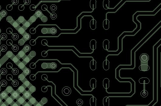
    1)      The routing described can be found on the C6678 EVM.  The information is on the Advantech website.  The receive pairs are on the outer two rings allowing these pairs to be routed away from the C6678 on the top layer.  To achieve this the pairs on the second ring need to split around the ground ball on the outer ring but this discontinuity shouldn’t be a problem.  This is shown below.


    2)      The statement “simple board stack-up” refers to a board without microvias or multiple stacks.  We’re referring to a board stack-up where all vias are drilled completely through the board.

    3)      The only way to ensure that the stub isn’t going to adversely effect your signals is to simulate the trace.  To achieve the highest data rate we recommend using the top and bottom layer.

    4)      It depends on how drastic the changes are but a moderate change based on standard build practices shouldn’t effect your performance.

    5)      In order to operate the SerDes interfaces we do recommend that you use lower loss/high speed materials.  These materials were used on the EVM.

    6)      Standard vias should be fine.

    7)      It is correct that you can swap lanes and swap the P and N connections on a per lane basis to simplify routing.

  • Hi Bill

    Thank you for the answer - but i need additional clarifications on few of the questions.

    1) I am aware of this example - the end of those diff pairs are routed to a connector.

    In Our design The hyperlink connects 2 DSP .

    The four shown diff pars are RX(0-3)  which should be  connected to the other DSP to TX(0-3) pins.

    TX(0-3) pins are in the 4th and 5th ring in the other DSP. and thus can not be reached by traces on top layer ( where the DSP is mounted )

    Note: In our Design there are no series capacitors ( DC Block )

    As i can understand: this can be solved if a non usuall diff pair swap is allowed

     resulting in connecting RX pins from on DSP to RX pins in the other DSP - and TX to TX

    Can the DSP handle this kind of swap and "correct" it internally ?

    2) OK

    3) Are you aware of such simulations done by somebody else ? - what were the results ?

    4) is a +/- 10% change in impedance for a 4" length acceptable ?

    5) can you recommend any specific material ?

    6) OK

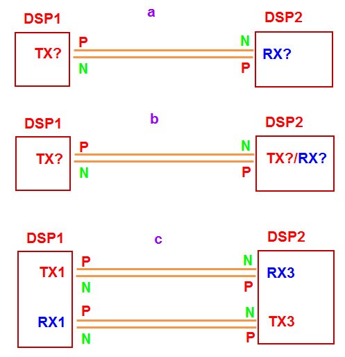
    7) see also item 1 : when you say "swap lanes"  to which of the option below you mean

    a) a TX from one DSP can be connected to any RX pins in the other DSP

    b) a TX from one DSP can be connected to any RX OR TX pins in the other DSP

    c)  2 pairs (lane) with same designation  (for example RX1 & TX1) from one DSP can be connected to the other DSP in other lane designation(for example TX3 & RX3 )

    while maintaining  that TX from one DSP is connected to RX in other DSP.

    In all variations P/N  can be swapped within the pair.

    see picture below

    8,9) You probably missed question 8,9 in my original post - can you answer those as well ?

    Thank you

    Roby

  • 1)      I was illustrating how you escape the receive pairs from the DSP.  The DSP to DSP example is similar to the example shown for the connectors.  In that case the transmit pair from the inner ring is dropped to the bottom of the board using the escape via.  The trace is routed on the bottom for a distance and then brought back to the top using a second via.  The trace is then routed directly to the receive balls.  The capacitors on the EVM were only included because of the connector.  They are not needed for DSP to DSP connection. 

    3)      Internal simulations were done to test whether the interface would operate a full speed.  These are not appropriate to your design.  You’ll have to simulate using your board layout.

    4)      +/- 10% change in impedance is acceptable.  That is the variation allowed on the EVM.

    5)      We don’t have a specific recommended material.  The material used on the EVM was a high performance FR4 material called FR4 IT168G.

    7)      The interface supports auto polarity detection and correction as well as auto lane identification and detection.  This means the following.

    Auto polarity detection and correction allows the P&N of a transmit differential pair to be connected to an N&P respectively of the receive pair.

    Auto lane identification and correction allows the transmit and receive pairs from one lane to be connected to the transmit and receive pairs of a different lane. 

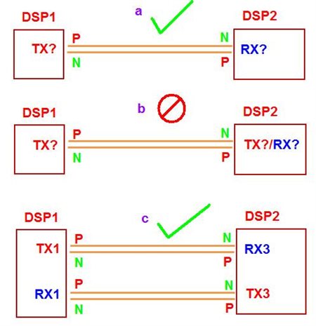
    In the examples you provided the HyperLink can be connected as shown in example a and example c but it can’t be connected as shown in example b.  A Tx pair must always be connected to an Rx pair.

    8 and 9 will require some additional research.  I’ll add an additional post once I have the information.  In general a longer SerDes interface requires a wider trace and the spacing between differential pairs should be as wide as possible in the range of 5x to 8x the width of the traces.

  • Bill

    1) I was sure that at least 4 diff pairs can be routed only on CS without the need for Vias

    But now i understand that all 8 Diff pairs will have 2 via and will be routed partially on TOP and partially on Bottom

    7) If we use all 4 Tx and RX pairs than only example c is allowed

    A lane which consists of one RX pair and TX pair with same designation can be swapped with other lane that has different designation

    In each pair P/N polarity can be changed

    Roby

    Thank you

  • Hi Bill,

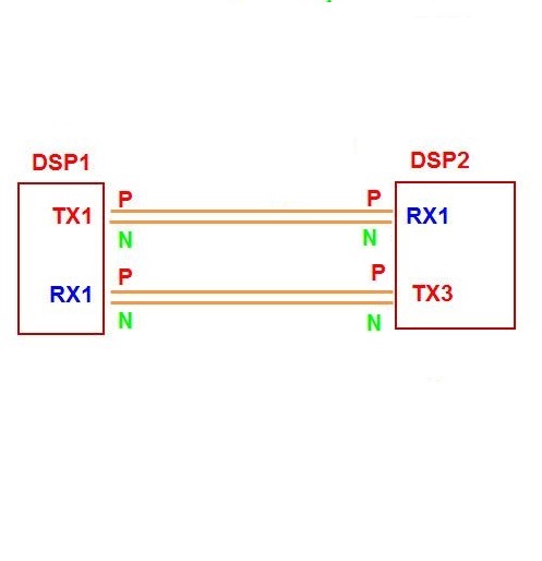
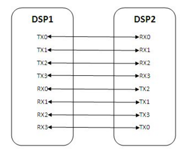
    We are designing the 6678 based Multi DSP board. We are thinking of using Lane swapping for Hyperlink . I have attached our configuration,please let me know whether it works or not  .

    Please confirm

    Regards,

    Sakthi.A


  • Hi Sakthi,
    I am putting your question in front of the designer to be sure I am answering correctly. Give me a few days to get the correct information for you.
    Regards,
    Bill
  • Hi Bill,

             Can you please speed up to answer our Hyperlink configuration. Since we need to finalise the design.

    Also how the DSP's will identify the lane swap of our configuration.   It is mentioned in the datasheet that Hyperlink serdes automatically detects the lane swap. Any Hyperlink registers needs to be  modified or monitored.

    thanks,

    Sakthi.A

  • Hi Bill,

               Any update please on our configuration.

    Regards,

    Sakthi.A

  • Hi Sakthi,

    I am sorry it took so long to get your answer but there were a number of team members that needed to be consulted. What I discovered is that a single lane of HyperLink cannot be connected as you have shown in your diagram. For all HyperLink implementations, all four lanes must be connected between the two DSPs. The HyperLink can disable the use of lanes to save power if only a single lane of throughput is needed, but all lanes must be physically connected between the two parts. This was not made clear in the Hardware Design Guide and I will update the guide to reflect this information.

    Regards,

    Bill

  • Hi Bill,

          We are going to use the lane swap for all four pairs. I have attached earlier only our concept of doing Hyperlink swap.   It made you to think differently. I have attached our actual lane swap concept with four lanes.

    Please find attached the swap image. Whether it is feasible or not . If it is  feasible ,please how the processor identifies the lane swap.Any registers to be monitored.

    Regards,

    Sakthi.A

  • Hi Sakthi,

    The lane swapping should not present a problem to the HyperLink interface. It will determine the connections and reassemble the data into the proper format at the far end. There isn't a set of registers that is provided by HyperLink to defining the swapping on the board. You will have to define a structure which identifies which DSP1 RX lane is connected to which DSP TX lane. You will need this information when running the software to tune the transmit and receive parameters for the SERDES interface. 

    Regards,

    Bill

  • Hi Bill,

    Thanks lot for your suggestion. We will look into that.

    Regards,
    Sakthi.A