This thread has been locked.

If you have a related question, please click the "Ask a related question" button in the top right corner. The newly created question will be automatically linked to this question.

boot loader for tms320c6678

Hi

I have a EVM6678 and i want to load a .out file to EEPROM with I2C. for this work i do following steps:

1. First, i built my own .out file with name MYPROJECT.OUT

2. I copied MYPROJECT.OUT to D:\Program Files\Texas Instruments\mcsdk_2_00_00_beta2\tools\bin2ccs

 and I double click on bin2ccs.bat and app.dat successfully built.

3. I set the dip switches in little endian/ no boot/ master I2c/ (SW3=1000,SW4=0000,SW5=0001,SW6=0000)

4. after that i copied the app.dat file to D:\Program Files\Texas Instruments\mcsdk_2_00_00_beta2\tools\writer\eeprom\evmc6678l\bin 

5. I load the eepromwriter_evm6678l.out file from D:\Program Files\Texas Instruments\mcsdk_2_00_00_beta2\tools\writer\eeprom\evmc6678l\bin to core0

6. I run the program and receive this message: "EEPROM programming completed successfully"

7. I push the PB :RST_FULL1 and i want MYPROJECT.OUT file will be loaded but this file do not load. 

is my work right?

  • really? any one can not answer my question?

  • Hi Armin,

    Refer the following readme file(C:\ti\mcsdk_2_01_02_06\tools\post\docs\Readme.txt) to build and flash the post boot example.

    POST example is a test program that can be programmed to I2C EEPROM and boot directly from I2C bus address 0x50 after POR.

    Please take a look at TMDXEVM6678L EVM Hardware Setup wiki link for boot mode selection.

    http://processors.wiki.ti.com/index.php/TMDXEVM6678L_EVM_Hardware_Setup

    Thanks,

  • Hi Ganapathi

    I want to load my .out file to EEPROM. I built a simple program. In my program, i sent a data to GPIO pins and i tested it and it worked.

    Now, i want to load this .out file to EEPROM and run it after POR.

    As i said before, i set dip switch on no boot mode/EMIF for loading to EEPROM. Then i change myproject.out to app.dat with double click bin2ccs.bat  on D:\ti\mcsdk_2_00_00_beta2\tools\bin2ccs

    After that i copied this app.dat to D:\ti\mcsdk_2_00_00_beta2\tools\writer\eeprom\evmc6678l\bin

    and i load eepromwriter_evm6678l.out to core 0 after connecting. 

    On next step, i load app.dat to memory map on the address 0x80000000. 

    After the data file is loaded into the memory, i run the program.

    when programming is completed, the console print "EEPROM programming completed successfully".

    I receive this message and myproject.out successfully loaded on EEPROM. 

    After that i turn off the board and set the dip switches to I2C mode and turn it on. So i want to see my data on GPIO pins but there is no data... 

  • Hi Armin,

    Please use latest MCSDK package for your testing.

    Refer my last reply to run post demo and valitate the i2c post boot. Share your example project and eeprom write project, i will try to reproduce your issue.

    Thanks,

  • Hi Ganapathi

    I run simple project with GPIO such this:

    set_reg(GPIO_DIR,0x00000000);
    set_reg(GPIO_SET_DATA,0x00005555);
    set_reg(GPIO_CLR_DATA,0x0000AAAA);
    delay_s(1);
    set_reg(GPIO_SET_DATA,0x0000AAAA);
    set_reg(GPIO_CLR_DATA,0x00005555);
    delay_s(1);

    I set GPIO direction for output and i set a data such as 5555 and then AAAA, 

    I build .out file and change the format to .dat with bin2ccs.bat and then use writer EEPROM project for write to EEPROM. 

    after writing to EEPROM, i power off the board and power on again but GPIO pins are in high-z mode. 

  • Hi Armin,

    Have you validated the post demo via i2c boot mode?

    Thanks,

  • Hi Ganapathi 

    I have a .OUT file that i want to load it to EEPROM. Can you tell me how can i load it and which project i must use? please tell me step by step. 

    Thanks for your attention

  • Hi Armin,

    Refer the following readme file(C:\ti\mcsdk_2_01_02_06\tools\post\docs\Readme.txt) to build and flash the post boot example and validate the I2C POST boot on your EVM.

    POST example is a test program that can be programmed to I2C EEPROM and boot directly from I2C bus address 0x50 after POR.

    Please take a look at TMDXEVM6678L EVM Hardware Setup wiki link for boot mode selection.

    http://processors.wiki.ti.com/index.php/TMDXEVM6678L_EVM_Hardware_Setup

    Thanks,

  • Hi Ganapathi

    Sorry for delay. Assume that i want to load a program to eeprom. POST program is a program which connect the EVM to PC through RS232. I don't want to use this program. Can i use ...\tools\writer\eeprom program for loading my program to eeprom with I2C?

  • Hi Armin,
    Thank you for the post. Please ensure to update the correct I2C address and memory sections while doing below steps.

    1. Update the script "post_romparse.bat or (.sh)" available in tools\post\evmc66xx\bin to covert the .out to .bin.
    2. Execute the romparse script.
    3. Use the \tools\writer\eeprom program for loading your program to eeprom with I2C. 

    Thank you.

  • Hi Raja

    Thanks for your response.
    Actually i don't know what i must do in addition to use the \tools\writer\eeprom program for loading my program to eeprom with I2C.
    For booting i just use writer program. What i must use from post program?
    When i updated the script "post_romparse.bat"," i2crom.ccs" will be generated and no .dat file exist.
    For generating "app.dat" i used "bin2ccs.exe" from ...\tools\bin2ccs.
    Can you explain boot loading step by step?
    Thank you
  • Hi Raja

    Thanks for your answer.
    I run this steps for eeprom bootloader:
    1. I built my project and ran successfully.
    2. I copied my.out file to ...\post\evmc6678l\bin and renamed it to "post_evm6678l.out".
    3. I updated the script "post_romparse.bat available in tools\post\evmc6678\bin to covert the "post_evm6678l.out" to "post_evm6678l.bin".
    4. I copied "post_evm6678l.bin" to ...\writer\eeprom\evmc6678l\bin.
    5. I turned on the board on no boot mode and connected to core 0 and loaded gel file and initialized ddr3.
    (no boot=off, on, on, on on, on, on, on on, on, on, on on, on, on, on)
    6. I set "eepromwriter_input.txt":
    file_name = post_i2crom.bin
    bus_addr = 0x50
    start_addr = 0
    swap_data = 0
    7. I loaded "eepromwriter_evm6678l.out" to core 0
    8. In memory browser section i loaded "post_evm6678l.bin" to "0x0C000000".
    9. Once the programming is completed successfully, i set the boot mode to I2C mode with bus address 0x50 and turned off the board
    (I2C=off, off, on, off on, on, on, on on, on, on, on on, on, on, on)
    10. After I turned on the board again, i don't see any effect

    In my project, i let a LED on GPIO15 and i blink it but after boot i don't see any blink.
  • Hi Armin,
    Please attach your application .out and .map file for reference. We will get back to you the steps.

    Thank you.

  • Hi Raja

    I sent .out and .map of my project in a new post on a zip file.
    Thanks for your response.
  • Hi,

    Have you test project .out file on No-boot mode? If no, Try to test the .out file in No-boot mode and validate the example is working properly or not.

    I have tested the LED play example on No-boot mode and I2C boot mode, it is working fine. Please share your whole project zip file.

    Thanks,
  • Hi Armin,

    I tried your .out file, it is not working as expected in "No boot" mode itself. It is not blinking LED as you mentioned.

    Please try with the attached .out file and let us know whether you are able to run from EEPROM. 

    led.zip

    Thank you.

  • Hi Raja

    I don't use LEDs on the board. I put an LED on the connector "TEST_PH1" between pin GPIO15 and ground. and blink it. My project is working correctly in no boot and I2C boot mode but i will use your project. In my way, your project is not loading too eeprom neither. What i must do in next step for I2C boot loading?

  • Hi Ganapathi

    As i said Raja, my project is working successfully on GPIO15 pin but when i loaded it to eeprom, i didn't see any effect on my LED.
  • Hi,

    DSP GPIO[0-15] : In normal operation mode, these signals are not driven by the FPGA so that the DSP can use them as GPIO pins. During the EVM power‐on or during the RESETFULLz asserted period, the FPGA will output the BM_GPIO switch values to the DSP on these pins so the DSP can latch the boot mode configuration.

    For more information refer C6678EVM Technical reference manual.

     
    Thanks,

  • Hi Ganapathi

    I have no problem with my project. i can see my output effect on GPIO15 but i can not see any effect after boot loading. Please tell me what is boot loading steps. I tried it on ".dat" and ".bin".

  • thank you Ganapathi

    This is my whole project in .zip.

    GPIO_15_Blink.zip

  • Hi Armin,

    1. I am able to convert led example attached earlier, program I2C and boot successfully on "I2C POST boot" mode (i2c addressed 0x50).

    eeprom50.bin

    O/P:

    Hello world strip on UART terminal and  4 LED's blink on EVM (D1-D4).

    2. I have converted your .out to .bin. Please find the below attachment.

    customer_project.zip

    Thank you.

  • Please program the .bin available in attached zip file, check the expected output on the LED(GPIO15).

    Thank you.
  • Hi Raja

    I programmed the .bin available in attached zip file which you sent with ...\mcsdk_2_01_02_06\tools\writer\eeprom\evmc6678l\bin\eepromwriter_evm6678l.out refer to ...\mcsdk_2_01_02_06\tools\writer\eeprom\docs\README.txt on no boot mode and  EEPROM programming completed successfully. After that i power off EVM and power on it again on I2C boot mode(off,off,on,off   on,on,on,on   on,on,on,on   on,on,on,on) but the EVM has no action. I tested both .bin file that you sent, "eeprom50.bin" and "post_i2crom.bin". Where is my fault?

  • Hi Armin,
    I have checked with factory team on this.
    1. In C6678 EVM, the GPIO15 is routed through FPGA and it is not recommended to test it on I2C boot mode.
    2. I hope you are able to run the eeprom50.bin successfully from I2C. I have tested this image on C6678 EVM.

    Please confirm. If the point 2 fails, please share the picture of your setup.

    Note: Please ensure to program POST i2c(0x50) by updating the text file available in writer directory.
    Thank you.
  • Hi Raja 

    With my way the eeprom50.bin which you sent not worked. I guess that my way is wrong. Can you tell me all steps of this project step by step?

  • Hi Armin,
    There is no issue with the steps followed.

    1. Are you able to run the POST example available in MCSDK?
    2. Please share the picture of your setup.

    Thank you.
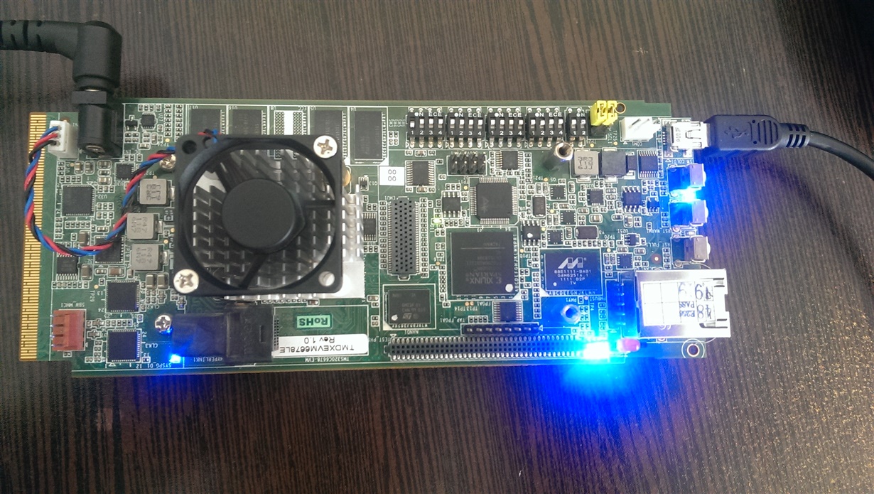
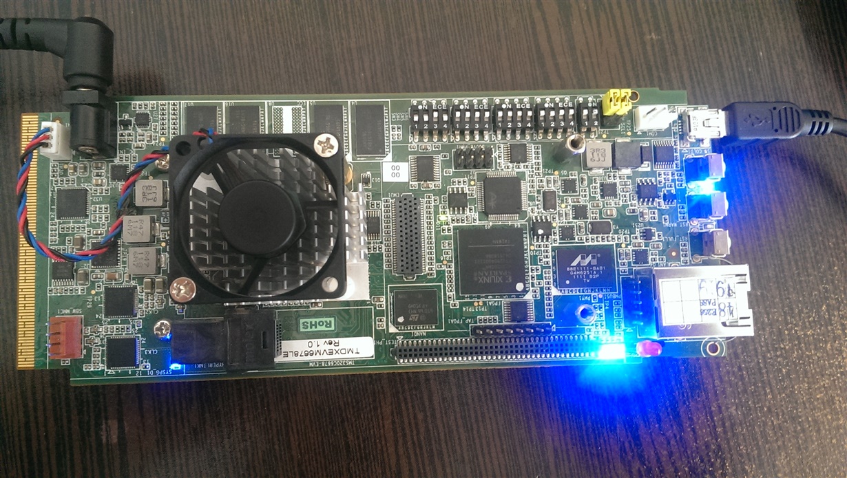
  • I set dip switches on no boot mode(the first image) and run eeprom project.

    after full reset i set the dip switches on I2C boot mode(the second image).

    I don't want run POST example. That example needs rs232 and hyper terminal but i don't want use them. I want program my project on eeprom. Can i do that without running POST example or not?

  • Case 1:

    I don't want run POST example. That example needs rs232 and hyper terminal but i don't want use them. I want program my project on eeprom. Can i do that without running POST example or not?

    I am asking you to check with pre-built POST image to narrow down the issue for further debugging. 

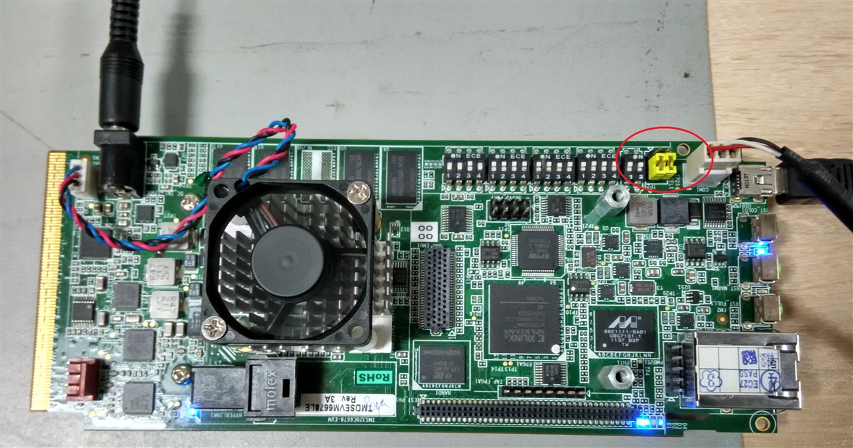
    Case 2:

    I would request to check I2C programming and run the example after changing the below jumper settings.

  • Hi Raja

    I changed jumper setting as you said but nothing changed. For now i have no system with DB-9. I will check the POST project when i get proper system.
  • Hi Raja

    I checked my way to other EVM and it worked. My EVM is Rev1.0 but other EVM was Rev 3.B. I don't know what is difference between them. Also just .bin file which you sent worked successfully. how did you build those .bin files?
  • Hi Armin,

    I am glad that you got a way to boot from I2C. Thank you for the update. 

    Also just .bin file which you sent worked successfully. how did you build those .bin files?

    I have attached two binaries in below post referred.  Which one worked?

    I have used post_romparse.bat available in customer_project.zip to generate the .bin files. 

    Thank you.

  • Hi Raja

    Thanks for your response.

    I load led project which you sent to eeprom on EVM Rev3 successfully.

    Now i have a question. I copy my ".out" to "...\tools\post\evmc6678l\bin" and rename it to "post_evm6678l.out" and then double click on "post_romparse.bat" and "post_i2crom.bin" will be made. Is it right?

  • Yes. Your understanding is correct.

    Thank you.
  • Thank you.
    Raja do you know what is differences between EVM Rev1 and Rev3?
  • Hi Armin,

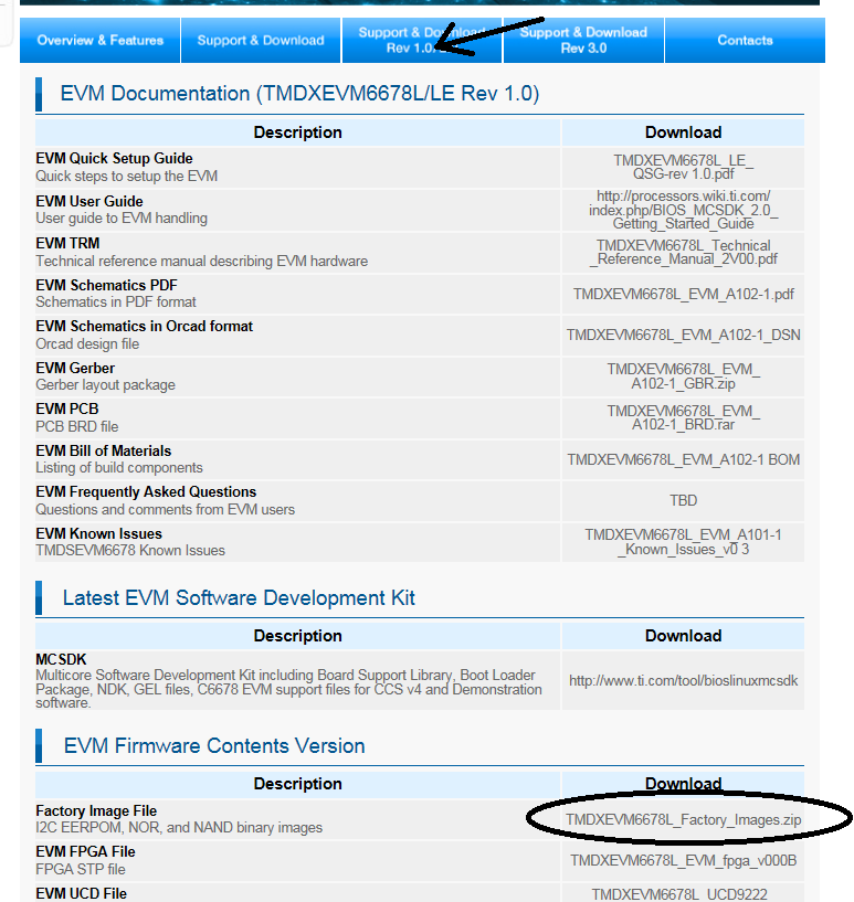
    No. Please check the EVM documents from below link,

    Please download the writer and other tools from above link. Please find the screenshot for reference. 

    Thank you.

  • Hi Raja 

    Thanks for your answers. I have another question about making bin file. In the "customer_project.rar" which you sent, was some files that i don't know how you built, such as ".ccs" and ".b". In source project this files don't exist. Do you know how can i build this files?

  • Hi Armin,
    The ".ccs" and ".b" files will be generated during the .bin file generation. Please execute the post_romparse.bat or post_romparse.sh to generate those files.

    Note: Make sure that the "Compiler" and "IBL" path's mentioned in the post_romparse are correct before executing it.

    Thank you.
  • Hi Raja

    Probably i set the path of "Compiler" and "IBL" wrong. I installed CCSv 5.2.1 and mcsdk_2_01_02_05 on "C:\CCS_5.2.1". Can you tell me what i must put for "Compiler" and "IBL" path?

    I set the path as following text but i don't have folder by name "C6000 Code Generation Tools 7.4.0". How can i install "Code Generation Tools"?:

    set C6000_CG_DIR="C:\CCS_5.2.1\C6000 Code Generation Tools 7.4.0"
    set TARGET=6678
    set ENDIAN=little
    set IBL_ROOT_DIR="..\..\..\boot_loader\ibl"
    set PATH=%PATH%;%SystemRoot%\system32;%SystemRoot%;

  • Hi Armin,

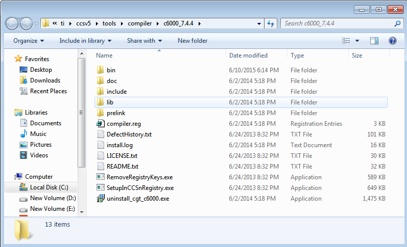
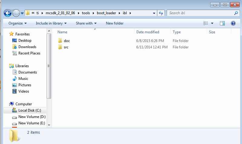
    It will be installed along with CCS. Attached the screenshot of the directory contents to verify at your end.

    Compiler - Code Generation Tool(CGT):

    IBL:

  • Hi Raja
    I downloaded code generation tool and set on "C:\CCS_5.2.1\C6000 Code Generation Tools 7.4.0". Also in "post_romparse.bat" i set this path:

    set C6000_CG_DIR="C:\CCS_5.2.1\C6000 Code Generation Tools 7.4.0"
    set TARGET=6678
    set ENDIAN=little
    set IBL_ROOT_DIR="C:\CCS_5.2.1\mcsdk_2_01_02_05\tools\boot_loader\ibl"
    set PATH=%PATH%;%SystemRoot%\system32;%SystemRoot%;

    I copy LED.out and LED.map which you sent in "mcsdk_2_01_02_05\tools\post\evmc6678l\bin" and rename it to "post_evm6678l.out" and "post_evm6678l.map" but when i double click on "post_romparse.bat", anything not happen and this work doesn't build"post_i2crom.bin". I don't know what is wrong?
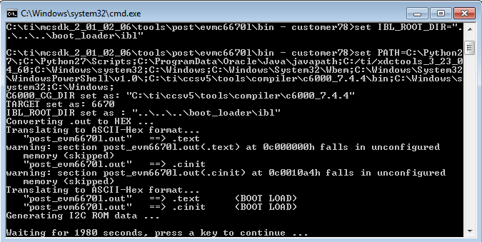
  • Please ensure that each command in the .bat file passes. Please find the console log for reference. Also recommend you to use latest MCSDK 2.x.

    Thank you.

  • Hi Raja

    I installed ccsv5.5 and mcsdk_2_01_02_06 again and finally i can build .bin from .out. 

    Thank you a lot for your good helps.

  • Hi,

    Ok, Glad to hear and thanks for the update.

    All the best with development.
  • Hi Armin,

    Thank you for the update.