This thread has been locked.

If you have a related question, please click the "Ask a related question" button in the top right corner. The newly created question will be automatically linked to this question.

66AK2H12 USB_CLK waveform

Other Parts Discussed in Thread: CDCM6208

Hi,

I check the differential clock of USB_CLK on K2H EVM.
I confirmed output clock of CDCM6208(U19: Pin #29).

Please refer to the following image, USB_CLK is not like pulse wave.

  USB_CLK(CDCM6208(U19: Pin #29))
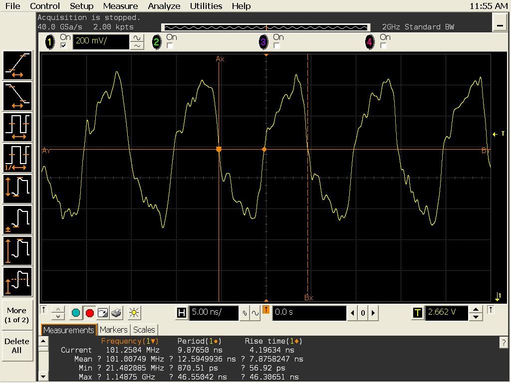

However, when I measured the DDR3A_CLK, it is observed pulse wave.

  DDR3A_CLK(CDCM6208(U19: Pin #32)).
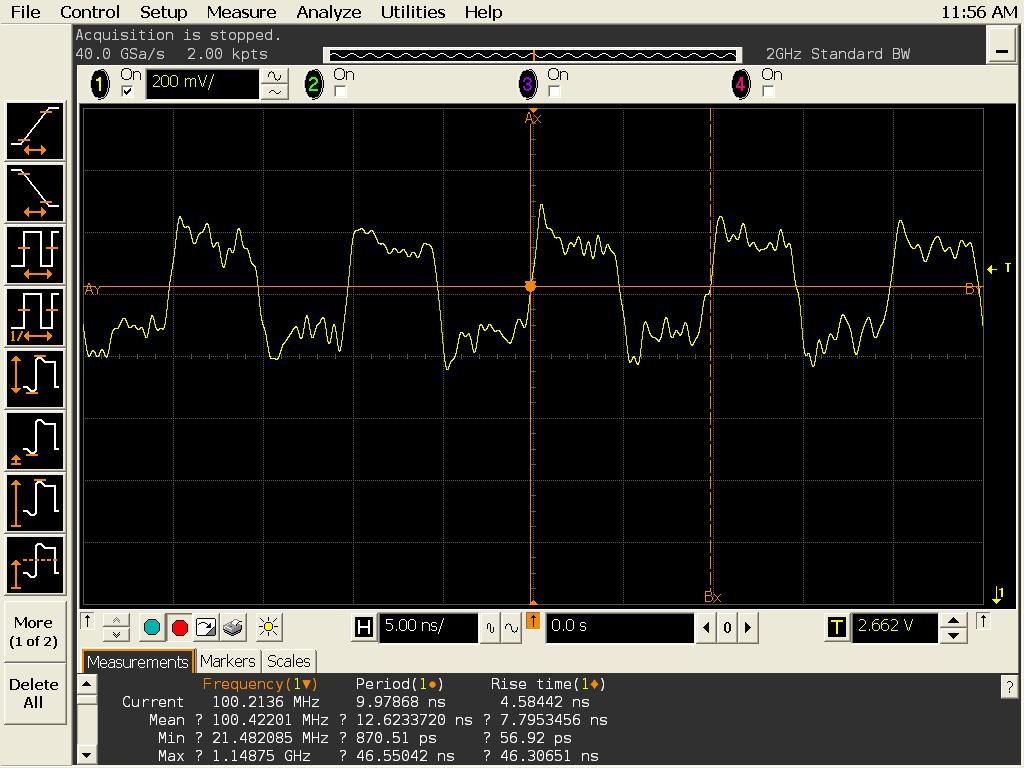

Why USB_CLK can not be observed pulse wave?

K2H EVM is not have AC-coupling capacitors at USB_CLKP/M.
Does differential clock of USB Phy not need AC-coupling?


Best regards,
H.U

  • Hello H.U,


    K2H EVM is not have AC-coupling capacitors at USB_CLKP/M.
    Does differential clock of USB Phy not need AC-coupling?


    Yes, the USB reference clock is supposed to be AC coupled. I am not sure why they have not provided AC coupling capacitors in EVM. But i see zero ohm resistor in clock lines which could be a place holder for AC coupling caps. Could you please try mounting AC caps in place of zero ohm resistor and check the waveform.

    However i will also check about this discrepancy.

    Regards,
    Senthil

  • Hi, Senthil

    Sorry, I can not try changing zero ohm registors to AC capcoitors immediately.
    So, I want to try this modification after that to clear whether USB reference clock has to be AC coupling.

    Best regards,
    H.U
  • Hello H.U,

    I have requested the team to get this answered. Due to festival holidays, the response will be delayed.

    Thanks for your patience.

    Regards,
    Senthil
  • Hi, Senthil

    I am waiting for your comment.
    Any update on this issue?

    Best Regards,
    H.U

  • Hello H.U,

    The USB reference clock requires AC coupling and termination to operate correctly with LVPECL and LVDS drivers. I am not sure why the EVM does not have AC coupling capacitors. You are encouraged to contact Advantech if you need more clarity on this.

    Regards,
    Senthil
  • Hello H.U,

    Besides seeing the difference in clock waveform between USB and DDR, are you seeing functional issue with USB?

    The USB internal PHY does includes the AC coupling capacitor, that is the reason the EVM does not provide AC coupling capacitor externally. If you are not seeing any functional issue, then leave the clock as it is. If you do see the issue that is caused by the clock’s common mode voltage not getting filtering out, then I would recommend putting the capacitor on the clock lines.

    Regards,

    Senthil


  • Hello, Senthil

    Thank you for your reply.

    I do not have USB functional issue for now.
    However, I can not understand the reason why USB_CLK cannot be observed pulse wave.
    It seems that USB_CLK does not meet the USB clock requirement.

    You say that "If you are not seeing any functional issue, then leave the clock as it is."
    Is this means that the USB_CLK( I have measured ) is supposed waveform?

    Best regards,
    H.U

  • Hi, Senthil

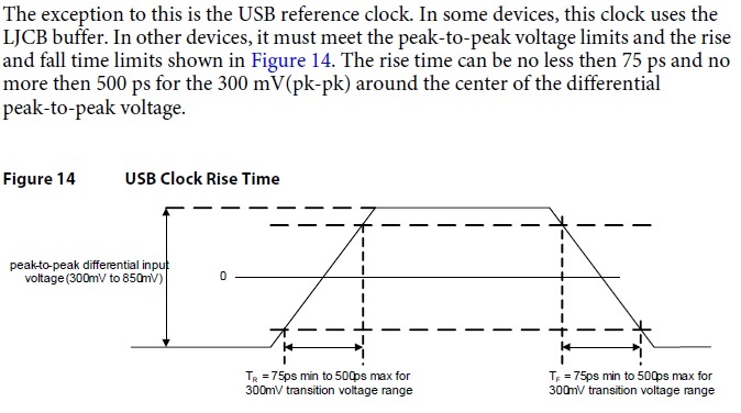
    USB_CLK waveform that I have measured do not meet the rise and fall time requirement as following.


    "Hardware Design Guide for Keystone 2 Devices(SPRABV0)"


    My customers board has the same hardware configuration as EVM, So they have observed the same USB_CLK waveform.
    Does TI ensure safe operation at this USB_CLK waveform?

    Best regards,
    H.U

  • Hello H.U,

    We are stilling working with our third-party ID vendor to finalize the clock requirement for USB and may need to update the datasheet and the design guide once the requirement is finalized. For now, our recommendation is for LVDS output, place AC coupling capacitors on CLKP/N, and also 100ohm termination between CLKP/N.

    Regards,
    Senthil
  • Hi, Senthil

    My customer's board design deadline is approaching.
    So, please tell me the schedule that this requirement specifications to fix.

    And, you say that we need AC coupling and 100ohm termination for USB CLKP/N.
    Is there a possibility that your recommendation may not need by result of your consultation?

    Best regards,
    H.U

  • H.U

    For LVDS output feeding the USB clock input, our current recommendation is to place the AC coupling capacitor, plus the 100ohm termination for the differential clock. With 100ohm termination designed on the board, it can be removed if not needed. But if reflection becomes an issue, then 100ohm can be populated.

    Thanks
    David

  • Hi, David

    Thank you for your reply.
    I was understanding about the handling of AC coupling capacitor and 100ohm termination.

    When will your USB clock requirement be decided?
    We want to avoid the design change as much as possible.

    Best regard,
    H.U

  • Hi, David

    Please update about your USB_CLK required specifications and consultation result of your third-party ID vendor for USB clock requirement.
    Still specification of USBCLK(tr(USBCLK)/tf(USBCLK)) is TBD status in 66AK2Hxx datasheet.

    Best regards,
    H.U

  • Hi,

    Can you tell me about the progress on this?

    It has been standing a long time.

    Best regards,

    H.U

  • Hi, David

    I would not like to prompt you, but would you please respond to above issues?

    Best regards,
    H.U

  • H.U

    Sorry for the delay, we are still discussing this with our IP vendor. Is there a particular part of the clock spec the customer is looking for?

    Thanks

    David

  • Hi, David

    Thank you for your reply.

    First of all, we hope that becomes clear the following points.

    1. Eventually 100 ohm termination is required or not for USB clock input.
    2. Specification of USBCLK(tr(USBCLK)/tf(USBCLK)) in 66AK2Hxx datasheet.

    Best regards,
    H.U

  • Hi, David

    Two months have passed since then previous post...
    Please any update, and tell me your update schedule.

    Best regards,
    H.U

  • H.U

    Below is the reference clock spec.

    I recommend having the 100 termination across CLKP/N, it can be removed if not needed.

    Thanks

    David

    FREF_CLK

    Reference clock frequency

    100

    MHz

    FREF_OFFSET

    Reference clock frequency offset

    -300

    300

    ppm

    RMSJREF_CLK

    Reference clock random jitter (RMS)

    3

    ps

    REF_CLK_SKEW

    Reference clock skew

    200

    ps

    DJREF_CLK

    Reference clock cycle-to-cycle jitter

    150

    ps

    DCREF_CLK

    Duty cycle

    40

    60

    %period

    Vp

    PHY analog and digital Super-Speed supply

    0.8075

    0.85

    0.8925

    Volts


    VCMREF_CLK

    Common mode input level

    Vss

    Vp

    Volts

    VCMREF_CLK

    Common mode input level

    VSS + VDREF_CLK/4


    Vp - VDREF_CLK/4


    Volts

    VDREF_CLK

    Differential input swing

    0.3

    Vp * 2

    Volts peak-to-peak differential

    VIH

    High-state input

    VCMREF_CLK + 75mV


    Vp

    Volts

    VIL

    Low-state input

    Vss


    VCMREF_CLK - 75mV

    Volts


    SWREF_CLK

    Differential input slew rate

    0.6


    4

    V/ns

  • Hi, David

    Thank you for your reply.

    I have few questions about your answer.

    1. VCMREF_CLK spec is defined twice.
       One is Vss(Min) to Vp(Max), other is (Vss + VDREF_CLK/4)(Min) to (Vp -VDREF_CLK/4)(Max).
       What's the defference?

    2. Do not USBCLK rise time and fall time constraints?

    Best regards,
    H.U

  • H.U

    The first VCMREF_CLK is a generic spec, the second one is more explicit based on the VDREF_CLK swing limit, you should follow the second one.

    Would you please give more detail on the second question? The slow rate for the clock is defined as part of the spec.

    Thanks
    David