This thread has been locked.

If you have a related question, please click the "Ask a related question" button in the top right corner. The newly created question will be automatically linked to this question.

srioboot_helloworld_evmc6657l program is not working with EVM6657?

Hi,

i am using  EVM6657 with CCSV5.5  and trying to test srioboot_helloworld_evmc6657l example . i try to run second core, so one of the TI people told me to use this example. i am using this example but core 0 will not start core 1. i debugged and found that i can't able to write in KICK0,KICK1 and IPCGR registers. they are zeroes. i hope the TI has already tested this program.please tell me why this is not working?

do i have to change any code composer version, as i am using now CCSV5.5 with bios 6.35.4.50.

Thanks,

Ram.

  • Hi Ram,

    Ram: said:
    i try to run second core, so one of the TI people told me to use this example.  

    We have asked you to refer this code snippet to wake up the secondary cores of DSP.

    Ram: said:
      i try to run second core, so one of the TI people told me to use this example. i am using this example but core 0 will not start core 1. i debugged and found that i can't able to write in KICK0,KICK1 and IPCGR registers. they are zeroes. i hope the TI has already tested this program.please tell me why this is not working? 

    I think, you were not following the correct steps to run the SRIO boot example. Please refer the detailed procedure document available in below path of MCSDK installation directory.

    PATH: ..:\ti\mcsdk_2_0x_0x_0x\tools\boot_loader\examples\srio\docs

    Ram: said:
     do i have to change any code composer version, as i am using now CCSV5.5 with bios 6.35.4.50. 

    No need to change CCS or BIOS for this.

    Thank you.

  • Hi Rajasekaran,

    i rebuild the program and try to download directly using onboard jtag emulator.  i haven't tried in the way the document says.

    but i hope it should work. why i am doing is just to see the difference between our custom board and TI EVM board. but the results are same.

    but if i load the program using onboard jtag emulator it should work, the program is loading perfectly and i am able to debug, but only i can't write into the KICK0,KICK1 and IPCGR registers.

    Thanks,

    Ram.

  • Hi ,

    do you know why can't able to write in IPCGR register(0x02620244). if i can't write 1 in this register the core 1 does not get any interrupt.please tell me what i have to change.whether i have to enable some thing like "CorePac INTC"  to generate interrupt.

    i saw the spec sprugw4a.pdf(keystone architecture chip interrupt controller) and specifies as below. IPCGR.docx

    Thanks,

    Ram.

  • Hi Rajasekaran,

    have you found anything why can't i am able to write in IPGCR(0x02620244) register for core1? but the sprugw4fa.pdf says when it creates an interrupt from core 0 to core 1, it should return 1 in IPCGR but it is returning zero.

    Thanks,

    Ram.

  • Ramada,

    - Looking at some other forums it does not seem that you need to read back the IPCG bitfield at all:
    e2e.ti.com/.../667678
    Since you will always read 0 you can not read back to check if writing to IPCG bitfield did work.
    You have to check the according flag in EVTFLAG2 to see if the interrupt got triggered.

    - The basic steps to interrupt the 2nd Core from the 1st core are given as well in the below post:
    e2e.ti.com/.../169360
    I guess something comparable is used in the different boot example from:
    \ti\mcsdk_2_0x_0x_0x\tools\boot_loader\examples\srio\docs

    To get started try on the EVM the procedure described in this post to see if the 2nd core jumps to the entry point specified in the BOOT MAGIC address.

    Hope it helps.

    Anthony

  • Also the below wiki page might be useful. It gives an high level view of the Keystone Interrupt mecanism:
    processors.wiki.ti.com/.../Configuring_Interrupts_on_Keystone_Devices

    A.
  • Hi Anthony,

    not succeeded. can you please try on the evm board on your place, with this srio_boot_example and please give me feedback it works or not, and with some screen shots, how the debugger looks if it works.
    i think if i am successful with the evm board, its easy for me to test finally on my custom board.

    Thanks,
    Ram.
  • Hi Ram,

    I don't have a C66x EVM available. I will try to ask somebody to make the test. In the mean time lets try the following sequence in 2)b) below:

    1) Boot sequence:

    The boot sequence is as follow:

        - During the boot process, the boot loader code is loaded into the L2 of Core 0 (ie corePac0) from the ROM.

        - The following L2 range (for C665x: start address 0x008EFD00 and end address 0x008F FFFF - see SPRS814B page 14) in all corePacs are reserved for the boot code. User should not overwrite this area.

        - All the other Cores will execute an IDLE.

        - User should load the image into the L2 of CorePacs they want to boot up. In your case Core 1.

        - Before setting the BOOTCOMPLETE, the user should also set the start address of the code in the respective BOOT MAGIC ADDRESS of the CorePac (Core 1 in our case) L2.

        - Finally, the user image should also write the IPC interrupt register to bring the required corePacs (Core 1 in our case) out of IDLE.

    2) How to check it is working?

    a) I would guess that when the Core1 has written to IPCG bitfield then an interrupt is generated.

    Q: Using CCS do you see any flag being set in the EVTFLAG2 register ?

    b) To check the boot and wake up sequence from CCS  might not be straight forward. The bellow post post gives an high level procedure:
    https://e2e.ti.com/support/dsp/c6000_multi-core_dsps/f/639/p/415380/1483616#1483616

    To be able to simply test it in CCS I guess we can try the following sequence:

    -> Create a CCS project based on the example 1 from this link:
    http://processors.wiki.ti.com/index.php/BIOS_MCSDK_2.0_User_Guide?keyMatch=led_play_ddr3&tisearch=Search-EN#Examples

    - >We want it to be executed on Core 1 so modify the linker command file (.cmd file) so that it fits in Core 1 L2 SRAM in a range NOT used by the boot loader (see 1 above).
    I think you have to use the memory area described as CorePac1 L2 SRAM in the memory map (ie in the range from 0x118EFD00 to 0x118F FFFF) so that the CCS loader knows explicitely that it is to be loaded in the CorePac1 L2 SRAM.

    Also you might need to keep only the Led portion of the example and reduce stack, heap side in order to have the code fit in the remaining CorePac1 L2 SRAM memory.

    -> Build the example and look at the .map file to get the entry_point

    -> Create a CCS project for Core 0 with the according wake up sequence from:
    https://e2e.ti.com/support/dsp/c6000_multi-core_dsps/f/639/p/421348/1505058#1505058
    For the BOOT MAGIC ADDRESS use the entry point from the previously built example 1 and build this project.
    I am not sure if any address conversion is needed here, I guess that using the same address should be fine. Check the memory map of the device at page 13 of the SPRS814B.

    - >In CCS: connect Core 0. Don't connect or initialize at all Core 1.

    -> Load the Core 0 wake up code but don't run it yet.

    -> Load the example 1. CCS should load it in CorePac1 L2 SRAM (n the range from 0x118EFD00 to 0x118F FFFF). Check with the memory view that it is the case.

    -> Run Core 0.

    -> Terminate the CCS debug session.

    -> Now Core 1 should have jumped to the entry point of the code manually loaded in CorePac1 L2 SRAM so you should see some Led blinking.

    As mentioned already I don't have a C6657 EVM so I can not test it but it should be quite close to a working sequence.

    Anthony

  •  

    Hi,


    Thank you for your support.

    1) Boot sequence:  i understood,This is not the ccs with jtag booting , for eg spi booting. is this right?The boot sequence,what i am doing with my custom board is like this:

    (1) first generate an .out file with the ccs. and convert to .bin and using spi boot i am loading to the DSP. 

    User should load the image into the L2 of CorePacs they want to boot up. In your case Core 1.

    how can i load in this process to core1?by default in my spi boot mode it automatically loads to core0. is this right?

    i understood the boot mechansim like this:

    now on my customboard, the booting is working fine through spi boot mode. i load to the .bin file( i hope by default it loads to core 0) i generated.

    and i think to run the core 1.

     i have to make new out file including the wakeupcode for core 1 , including the core 1 interrupt generation. in my case i want to use the same application on core 1, so i include _C_init in the boot_magic_addr  in main(). so automatically the core 1 starts and loads again the same application. so if i make the new .out file and .bin file with these changes. the .bin file is loaded through spi boot mode,default to core 0 (i hope) and with the wake up code it starts the second core and runs(in my case same application).

    thats why i am trying to generate a new .out file with the ccs and test at the beginning with JTAG and to use the same .out file through spi boot mode.

    Thanks,

    Ram.

  • Ramana_Munich said:

    1) Boot sequence:  i understood,This is not the ccs with jtag booting , for eg spi booting. is this right?

    Yes the sequence in 1) is for the RBL. The complete RBL boot sequence is documented in section 2.2 of SPRUGy5C.

    CCS does not follow this procedure as it has its own loader and can from the .out file determine at what address the different code/data section need to be loaded.

    Ramana_Munich said:

    User should load the image into the L2 of CorePacs they want to boot up. In your case Core 1.

    how can i load in this process to core1?by default in my spi boot mode it automatically loads to core0. is this right?

    - I was assuming that you wanted to test the wake up using CCS and not specifically booting from SPI.
    In the case I described, CCS is used to load the 2 executable in Core 0 and Core 1 at the address defined in the linker.cmd file (ie L2 SRAM of core 0 and L2 SRAM of core 1).
    The purpose here was just to show how to simply wake up core 1 from core 0 using CCS.

    - In case of SPI boot see SPRUGYC at section 3.8:
    The RBL code will load image and copy it at the address it found in the boot table. This is automatic.
    The address it copies it too are the one you defined in the Linker .cmd file. You can check the .map file to double check that the actual addresses the linker uses matches what you want.
    The memory can be any RAM (like L2 SRAM, DDR, ..etc) provided that:
       - The DDR has been initialized before using it
      -  You use the L2 SRAM area that is not already used by RBL (see see SPRS814B page 14)

    Ramana_Munich said:
    ( i hope by default it loads to core 0)

    Yes, RBL (run by Core 0) loads the image in the memory and at the end of the boot and Core 0 starts to execute (ie jumps to the entry point of this application).

    In the code executed by Core 0 you need to have some code to wake up Core 1 otherwise Core 1 will stay in IDLE and never wake up.

    Ramana_Munich said:
    so automatically the core 1 starts and loads again the same application. so if i make the new .out file and .bin file with these changes. the .bin file is loaded through spi boot mode,default to core 0 (i hope) and with the wake up code it starts the second core and runs(in my case same application).

    I think that Core 0 need to load the image for Core 1 as well. I think that there are 2 possible scenario:

    a) There is 1 single application for Core 0 and Core 1 and RBL loads it in an address accessible by both Core 0 and Core 1.The wake up portion of the application will need to be run by Core 0 only. When Core 1 wakes up it will run the same image (located at the same address) as Core 0.

    b) There are 2 separate application for Core 1 and Core 0:
    - If the 2 application are merged in a single .bin image then the RBL can load both application as part of the boot procedure.
    Core 0 wake up core 1 that will run it's own application thta was pre-loaded by the RBL.

    - If the 2 application are not merged in a single image but burned as separate image in the FLASH then as part of Core 0 application you need to have a 2nd level bootloader that will load the Core 1 image from Flash and copy it to the according RAM.

    Ramana_Munich said:
    thats why i am trying to generate a new .out file with the ccs and test at the beginning with JTAG and to use the same .out file through spi boot mode.

    Yes I would suggest to test first with CCS (without booting from SPI) with a simple procedure to wake up Core 1 from Core 0. See my previous post. When you have that working then you can move forward to SPI boot.

    Anthony

  • Hi Ram,

    I am able to wake up the secondary core from primary core. Please try below procedure in EVM and get back to me if you have any issues.

    1. Set the EVM in "No Boot" mode, connect to core0 and use gel file to initialize the core0.

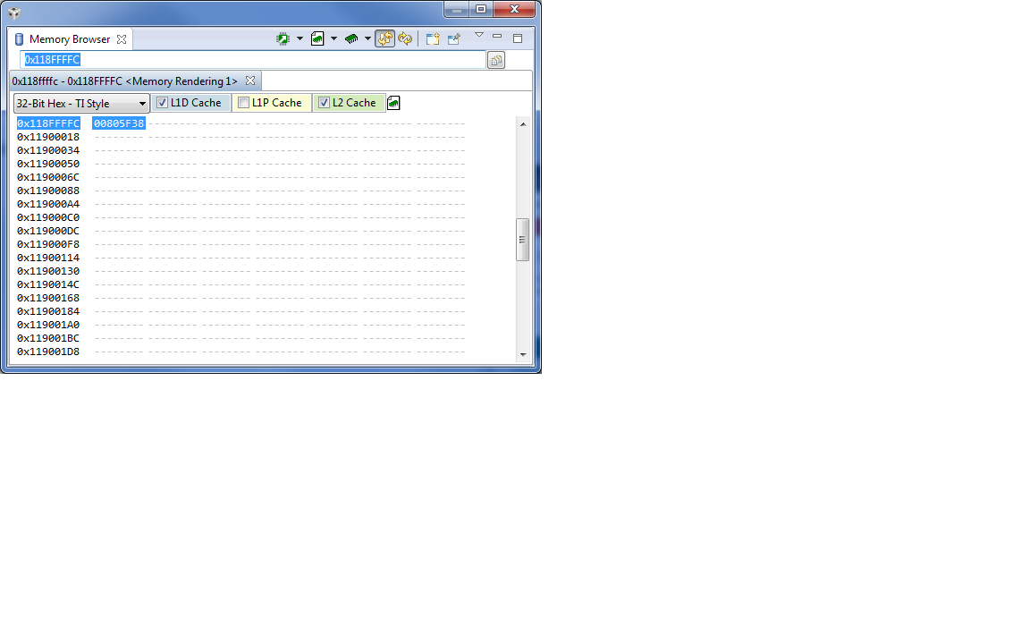
    2. Go to memory browser, read the address 0x118FFFFC and make a note of it.

    3. Build the attached source and load and run on core0.

    4. After completion of execution, core0 will wait in busy loop(while(1)). Pause the debugging.

    5. Go to memory browser, enter the address 0x118FFFFC.=> 0xBABEFACE

    7142.5008.evmc6657l.gel

    5584.srioboot_helloworld.c
    /******************************************************************************
     * Copyright (c) 2011 Texas Instruments Incorporated - http://www.ti.com
     *
     *  Redistribution and use in source and binary forms, with or without
     *  modification, are permitted provided that the following conditions
     *  are met:
     *
     *    Redistributions of source code must retain the above copyright
     *    notice, this list of conditions and the following disclaimer.
     *
     *    Redistributions in binary form must reproduce the above copyright
     *    notice, this list of conditions and the following disclaimer in the
     *    documentation and/or other materials provided with the
     *    distribution.
     *
     *    Neither the name of Texas Instruments Incorporated emac the names of
     *    its contributors may be used to endorse or promote products derived
     *    from this software without specific prior written permission.
     *
     *  THIS SOFTWARE IS PROVIDED BY THE COPYRIGHT HOLDERS AND CONTRIBUTORS
     *  "AS IS" AND ANY EXPRESS OR IMPLIED WARRANTIES, INCLUDING, BUT NOT
     *  LIMITED TO, THE IMPLIED WARRANTIES OF MERCHANTABILITY AND FITNESS FOR
     *  A PARTICULAR PURPOSE ARE DISCLAIMED. IN NO EVENT SHALL THE COPYRIGHT
     *  OWNER OR CONTRIBUTORS BE LIABLE FOR ANY DIRECT, INDIRECT, INCIDENTAL,
     *  SPECIAL, EXEMPLARY, OR CONSEQUENTIAL DAMAGES (INCLUDING, BUT NOT
     *  LIMITED TO, PROCUREMENT OF SUBSTITUTE GOODS OR SERVICES; LOSS OF USE,
     *  DATA, OR PROFITS; OR BUSINESS INTERRUPTION) HOWEVER CAUSED AND ON ANY
     *  THEORY OF LIABILITY, WHETHER IN CONTRACT, STRICT LIABILITY, OR TORT
     *  (INCLUDING NEGLIGENCE OR OTHERWISE) ARISING IN ANY WAY OUT OF THE USE
     *  OF THIS SOFTWARE, EVEN IF ADVISED OF THE POSSIBILITY OF SUCH DAMAGE.
     *
     *****************************************************************************/
    
    /**************************************************************************************
     * FILE PURPOSE: Boot Hello World Example
     **************************************************************************************
     * FILE NAME: boot_helloworld.c
     *
     * DESCRIPTION: A simple hello world example demonstrating boot.
     *
     ***************************************************************************************/
    #include <stdlib.h>
    #include <stdio.h>
    #include <string.h>
    #include "platform.h"
    
    #define DEVICE_REG32_W(x,y)   *(volatile uint32_t *)(x)=(y)
    #define DEVICE_REG32_R(x)    (*(volatile uint32_t *)(x))
    
    #define CHIP_LEVEL_REG  0x02620000
    #define KICK0           (CHIP_LEVEL_REG + 0x0038)
    #define KICK1           (CHIP_LEVEL_REG + 0x003C)
    
    /* Magic address RBL is polling */
    #ifdef _EVMC6657L_
    #define MAGIC_ADDR          0x8ffffc
    #endif
    
    #ifdef _EVMC6678L_
    #define MAGIC_ADDR          0x87fffc
    #endif
    
    #ifdef _EVMC6670L_
    #define MAGIC_ADDR          0x8ffffc
    #endif
    
    #define BOOT_MAGIC_ADDR(x)  (MAGIC_ADDR + (1<<28) + (x<<24))
    #define IPCGR(x)            (0x02620240 + x*4)
    
    #define NUMBER_OF_CORES 	2
    
    #define BOOT_MAGIC_NUMBER   0xBABEFACE
    
    #define BOOT_NUMBER0   0xAAAA5555
    #define BOOT_NUMBER1   0x11111111
    #define BOOT_NUMBER2   0x22222222
    #define BOOT_NUMBER3   0x33333333
    
    #define DDR_ADDR0       0x81000000
    #define DDR_ADDR1       0x82000000
    #define DDR_ADDR2       0x83000000
    #define DDR_ADDR3       0x84000000


    #define BOOT_UART_BAUDRATE         115200
    
    /* boot_helloworld version */
    char version[] = "01.00.00.01";
    
    /* OSAL functions for Platform Library */
    uint8_t *Osal_platformMalloc (uint32_t num_bytes, uint32_t alignment)
    {
    	return malloc(num_bytes);
    }
    
    void Osal_platformFree (uint8_t *dataPtr, uint32_t num_bytes)
    {
        /* Free up the memory */
        if (dataPtr)
        {
            free(dataPtr);
        }
    }
    
    void Osal_platformSpiCsEnter(void)
    {
        return;
    }
    
    void Osal_platformSpiCsExit (void)
    {
        return;
    }
    
    /******************************************************************************
     * Function:    write_uart
     ******************************************************************************/
    void
    write_uart
    (
        char*      msg
    )
    {
        uint32_t i;
        uint32_t msg_len = strlen(msg);
    
        /* Write the message to the UART */
        for (i = 0; i < msg_len; i++)
        {
            platform_uart_write(msg[i]);
        }
    }
    
    void
    write_boot_magic_number
    (
        void
    )
    {
        uint32_t                coreNum;
    
        coreNum = platform_get_coreid();
    
        DEVICE_REG32_W(MAGIC_ADDR, BOOT_MAGIC_NUMBER);
        
        while(1);
    }
    
    /******************************************************************************
     * Function:    main
     ******************************************************************************/
    void main ()
    {
        char                    version_msg[] = "\r\n\r\nBoot Hello World Example Version ";
        char                    boot_msg[80];
        platform_info           pform_info;
        uint32_t                coreNum, core;
    
        /* Initialize UART */
        coreNum = platform_get_coreid();
        if (coreNum == 0)
        {
            platform_uart_init();
            platform_uart_set_baudrate(BOOT_UART_BAUDRATE);
    
            printf("%s%s\n\n", version_msg, version);
    
            /* Unlock the chip registers */
            DEVICE_REG32_W(KICK0, 0x83e70b13);
            DEVICE_REG32_W(KICK1, 0x95a4f1e0);
    
            /* Writing the entry address to other cores */
            for (core = 1; core < NUMBER_OF_CORES; core++)
            {
                sprintf(boot_msg, "\r\n\r\nBooting Hello World image on Core %d from Core 0 ...", core);
                printf("%s\n",boot_msg);
                
                DEVICE_REG32_W(BOOT_MAGIC_ADDR(core), (uint32_t)write_boot_magic_number);
    
                /* Delay 1 sec */
                platform_delay(1);
            }
            for (core = 1; core < NUMBER_OF_CORES; core++)
            {
                /* IPC interrupt other cores */
                DEVICE_REG32_W(IPCGR(core), 1);
                platform_delay(1000);
            }
    
        }
        else
        {
            write_boot_magic_number();
        }
    
        while(1);
    }
    

    This means that core0 wakes up  core1 successfully. The value 0xBABEFACE  has been written by core1 from function "write_boot_magic_number()".

    Thank you.

  • Hi Rajasekharan,

    Thanks for the procedure.

    My setup: CCS with JTAG(EVM onboard).

    it works fine, even i changed the magic number it worked. but one important thing i observed is, i have to switch off and switch on the evm to get the right result. if i don't switch off and switch on the evm, it does not work. i.e if once switched on the evm, then at the first step works fine,then if i want to run one more time(or more times) same procedure it does not work. i think it needs everytime complete reset(POR reset). is it right? i think when we load the program using jtag, it resets the DSP. but i don't know which reset it give. system reset or cpu reset. i think power on reset(POR), system reset and warm reset gives the same effect, resetting the complete chip.cpu reset means for each core.

    i think the gel file you have given only does some initalization, i also tested in the otherway without gel file, first i loaded the ddr3_test project which initalises all the stuff. then i loaded this srio_boot_helloworld example, it works also. i hope gel does not include any mysterious things.

    i done in this way lot testing before, but now the major change from my side, is swiching on evm every time to make the test(works now).Please explain me why i have to do this?

    now i have to find why my custom board does not work. i included the wakeup code like this, but only missing is the switching on and off(POR). i will do in this way and try to find out.

    Thanks,

    Ram.

  • Hi,

    (1)setup used: EVM+onboard emulator

    it worked as the procedure told by Rajasekaran on the EVM, it worked only every time when i switch off and switch on the EVM,Please see my questions to Rajasekaran's , Please answer me if possible.

    (2)setup used: customboard+USB560 JTAG Emulator

    Today i am able to run on my custom board. it worked as follow. first i load my program using jtag emulator then it loads with the wakeupcode for core 1.then  i ran through the program at the end. i checked the 0x118ffffc , it does not have the magic number. then i terminate the program by clicking red button.

    Then i connected the target again(without loading program) and connected to the core 0, then checked the 0x118ffffc, then it shows the right magic number  what i am writing in core 1. i think it works only in this way. but what i don't understand is why i  have to terminate the program and connect again normally.

    (3) with SPI boot mode: i took the .out file from (2) and generated  .bin and loaded through our spi boot mode. DSP is booted successfuly. and then i want to check whether right magic address is written or not for core1. i used the traditional way, to use my jtag debugger to connect the target, but i don't see the right magic address. i don't know why. this is the last one i have to solve. i am using the application (a) mentioned by you for the spi boot mode. Do you have any idea?

    Thanks,

    Ram.

  • 1. I think, that is the expected behavior. I will try to get detailed information and post back.
    2. I am able read the magic address without connecting again. I just pause execution at core0 then read majic address.
    3. In SPI boot mode, I recommend you to toggle any user LED(GPIO) or out some message from UART from core1.

    Thank you.

  • Hi Raja,

    thank you for the fast response.

    2.for evm board, even i can pause  execution at core0 then read majic address.

    The EVM board is  exactly working as told by you in the last email.but one difference is as i told you in the last email, i have to switch off and switch on evm everytime.

    but for my custom board i have to terminate the debugging session after loading my program, and connect again to read the magic address. this is not the behaviour of evm board.but i don't know why this is behaving like this, whether i missing something in my code, what the gel file is doing in the initalization, any PSC(powersleep controller) i have to configure?

    3.i will try to toggle some led. but principally if i write some thing for core 1 in address 0x118ffffc during booting, then i have to read it back.even i am writing in our fpga for core 0, core 1, but i am getting back the core 0 but not for core 1.some thing is missing i hope.

    Thanks,

    Ram.

  • Hi Raja,

    if you have some time, please take the DDR3_RW_test project and change the code, to wake up core 1 and please run on the evm directly. and please tell me feed back.

    Thanks,
    Ram.
  • Hello ,

    Unfortunately no.

    The core 0 cannot wake up core 1. I follow the steps that are described in the previous post , but I do not the code for the uart.

    In the magic address  the write_boot_magic_address function address has been written.

    Thank you in advance

    George.

    I have attached the code that I try to execute.

    Please also find the target configuration

    <?xml version="1.0" encoding="UTF-8" standalone="no"?>
    <configurations XML_version="1.2" id="configurations_0">
    <configuration XML_version="1.2" id="Texas Instruments XDS2xx USB Onboard Emulator_0">
            <instance XML_version="1.2" desc="Texas Instruments XDS2xx USB Onboard Emulator_0" href="connections/TIXDS2XXUSB_onboard_Connection.xml" id="Texas Instruments XDS2xx USB Onboard Emulator_0" xml="TIXDS2XXUSB_onboard_Connection.xml" xmlpath="connections"/>
            <connection XML_version="1.2" id="Texas Instruments XDS2xx USB Onboard Emulator_0">
                <instance XML_version="1.2" href="drivers/tixds560icepick_d.xml" id="drivers" xml="tixds560icepick_d.xml" xmlpath="drivers"/>
                <instance XML_version="1.2" href="drivers/tixds560c66xx.xml" id="drivers" xml="tixds560c66xx.xml" xmlpath="drivers"/>
                <instance XML_version="1.2" href="drivers/tixds560cs_dap.xml" id="drivers" xml="tixds560cs_dap.xml" xmlpath="drivers"/>
                <instance XML_version="1.2" href="drivers/tixds560csstm.xml" id="drivers" xml="tixds560csstm.xml" xmlpath="drivers"/>
                <instance XML_version="1.2" href="drivers/tixds560etbcs.xml" id="drivers" xml="tixds560etbcs.xml" xmlpath="drivers"/>
                <platform XML_version="1.2" id="platform_0">
                    <instance XML_version="1.2" desc="TMS320C6657_0" href="devices/C6657.xml" id="TMS320C6657_0" xml="C6657.xml" xmlpath="devices"/>
                <device HW_revision="1" XML_version="1.2" description="C66x core" id="TMS320C6657_0" partnum="TMS320C6657" simulation="no">
                        <router HW_revision="1.0" XML_version="1.2" description="ICEPick_D Router" id="IcePick_D_0" isa="ICEPICK_D">
                            <subpath id="subpath_0">
                                <cpu HW_revision="1.0" XML_version="1.2" description="C66xx CPU" deviceSim="false" id="C66xx_0" isa="TMS320C66xx">
                                    <property Type="filepathfield" Value="..\..\My Documents\5008.evmc6657l.gel" id="GEL File"/>
                                <property Type="numericfield" Value="0x0" id="TraceDeviceId"/>
                                <property Type="choicelist" Value="0" id="Slave Processor"/>
                                </cpu>
                            </subpath>
                        <subpath id="subpath_1">
                                <cpu HW_revision="1.0" XML_version="1.2" description="C66xx CPU" deviceSim="false" id="C66xx_1" isa="TMS320c66xx">
                                    <property Type="filepathfield" Value="" id="GEL File"/>
                                    <property Type="choicelist" Value="1" id="Slave Processor"/>
                                <property Type="numericfield" Value="0x1" id="TraceDeviceId"/>
                                <property Type="choicelist" Value="0" id="bypass"/>
                                </cpu>
                            </subpath>
                        </router>
                    </device>
                </platform>
            </connection>
        </configuration>
    </configurations>
    

    /******************************************************************************
     * Copyright (c) 2011 Texas Instruments Incorporated - http://www.ti.com
     *
     *  Redistribution and use in source and binary forms, with or without
     *  modification, are permitted provided that the following conditions
     *  are met:
     *
     *    Redistributions of source code must retain the above copyright
     *    notice, this list of conditions and the following disclaimer.
     *
     *    Redistributions in binary form must reproduce the above copyright
     *    notice, this list of conditions and the following disclaimer in the
     *    documentation and/or other materials provided with the
     *    distribution.
     *
     *    Neither the name of Texas Instruments Incorporated emac the names of
     *    its contributors may be used to endorse or promote products derived
     *    from this software without specific prior written permission.
     *
     *  THIS SOFTWARE IS PROVIDED BY THE COPYRIGHT HOLDERS AND CONTRIBUTORS
     *  "AS IS" AND ANY EXPRESS OR IMPLIED WARRANTIES, INCLUDING, BUT NOT
     *  LIMITED TO, THE IMPLIED WARRANTIES OF MERCHANTABILITY AND FITNESS FOR
     *  A PARTICULAR PURPOSE ARE DISCLAIMED. IN NO EVENT SHALL THE COPYRIGHT
     *  OWNER OR CONTRIBUTORS BE LIABLE FOR ANY DIRECT, INDIRECT, INCIDENTAL,
     *  SPECIAL, EXEMPLARY, OR CONSEQUENTIAL DAMAGES (INCLUDING, BUT NOT
     *  LIMITED TO, PROCUREMENT OF SUBSTITUTE GOODS OR SERVICES; LOSS OF USE,
     *  DATA, OR PROFITS; OR BUSINESS INTERRUPTION) HOWEVER CAUSED AND ON ANY
     *  THEORY OF LIABILITY, WHETHER IN CONTRACT, STRICT LIABILITY, OR TORT
     *  (INCLUDING NEGLIGENCE OR OTHERWISE) ARISING IN ANY WAY OUT OF THE USE
     *  OF THIS SOFTWARE, EVEN IF ADVISED OF THE POSSIBILITY OF SUCH DAMAGE.
     *
     *****************************************************************************/
    
    /**************************************************************************************
     * FILE PURPOSE: Boot Hello World Example
     **************************************************************************************
     * FILE NAME: boot_helloworld.c
     *
     * DESCRIPTION: A simple hello world example demonstrating boot.
     *
     ***************************************************************************************/
    #include <stdlib.h>
    #include <stdio.h>
    #include <string.h>
    #include "platform_internal.h"
    #include "platform.h"
    
    #define DEVICE_REG32_W(x,y)   *(volatile uint32_t *)(x)=(y)
    #define DEVICE_REG32_R(x)    (*(volatile uint32_t *)(x))
    
    #define CHIP_LEVEL_REG  0x02620000
    #define KICK0           (CHIP_LEVEL_REG + 0x0038)
    #define KICK1           (CHIP_LEVEL_REG + 0x003C)
    
    /* Magic address RBL is polling */
    #ifdef _EVMC6657L_
    #define MAGIC_ADDR          0x8ffffc
    #endif
    
    #ifdef _EVMC6678L_
    #define MAGIC_ADDR          0x87fffc
    #endif
    
    #ifdef _EVMC6670L_
    #define MAGIC_ADDR          0x8ffffc
    #endif
    
    #define BOOT_MAGIC_ADDR(x)  (MAGIC_ADDR + (1<<28) + (x<<24))
    #define IPCGR(x)            (0x02620240 + x*4)
    
    #define NUMBER_OF_CORES     2
    
    #define BOOT_MAGIC_NUMBER   0xBABEFACE
    
    #define BOOT_NUMBER0   0xAAAA5555
    #define BOOT_NUMBER1   0x11111111
    #define BOOT_NUMBER2   0x22222222
    #define BOOT_NUMBER3   0x33333333
    
    #define DDR_ADDR0       0x81000000
    #define DDR_ADDR1       0x82000000
    #define DDR_ADDR2       0x83000000
    #define DDR_ADDR3       0x84000000


    #define BOOT_UART_BAUDRATE         115200
    
    
    uint32_t platform_get_coreid(void)
    {
        return (CSL_chipReadDNUM());
    }
    
    Platform_STATUS platform_delay(uint32_t usecs)
    {
        int32_t delayCount = (int32_t) usecs * 850000000;
        int32_t start_val  = (int32_t) CSL_chipReadTSCL();
    
        while (((int32_t)CSL_chipReadTSCL() - start_val) < delayCount);
    
        return Platform_EOK;
    }
    
    /* boot_helloworld version */
    char version[] = "01.00.00.01";
    
    /* OSAL functions for Platform Library */
    uint8_t *Osal_platformMalloc (uint32_t num_bytes, uint32_t alignment)
    {
        return malloc(num_bytes);
    }
    
    void Osal_platformFree (uint8_t *dataPtr, uint32_t num_bytes)
    {
        /* Free up the memory */
        if (dataPtr)
        {
            free(dataPtr);
        }
    }
    
    void Osal_platformSpiCsEnter(void)
    {
        return;
    }
    
    void Osal_platformSpiCsExit (void)
    {
        return;
    }
    
    /******************************************************************************
     * Function:    write_uart
     ******************************************************************************/
    void
    write_uart
    (
        char*      msg
    )
    {
        uint32_t i;
        uint32_t msg_len = strlen(msg);
    
        /* Write the message to the UART */
        for (i = 0; i < msg_len; i++)
        {
          //  platform_uart_write(msg[i]);
        }
    }
    
    void
    write_boot_magic_number
    (
        void
    )
    {
        uint32_t                coreNum;
    
        coreNum = platform_get_coreid();
    
        DEVICE_REG32_W(MAGIC_ADDR, BOOT_MAGIC_NUMBER);
    
        while(1);
    }
    
    /******************************************************************************
     * Function:    main
     ******************************************************************************/
    void main ()
    {
        char                    version_msg[] = "\r\n\r\nBoot Hello World Example Version ";
        char                    boot_msg[80];
        platform_info           pform_info;
        uint32_t                coreNum, core;
    
        /* Initialize UART */
        coreNum = platform_get_coreid();
        if (coreNum == 0)
        {
          //  platform_uart_init();
          //  platform_uart_set_baudrate(BOOT_UART_BAUDRATE);
    
            printf("%s%s\n\n", version_msg, version);
    
            /* Unlock the chip registers */
            DEVICE_REG32_W(KICK0, 0x83e70b13);
            DEVICE_REG32_W(KICK1, 0x95a4f1e0);
    
            /* Writing the entry address to other cores */
            for (core = 1; core < NUMBER_OF_CORES; core++)
            {
                sprintf(boot_msg, "\r\n\r\nBooting Hello World image on Core %d from Core 0 ...", core);
                printf("%s\n",boot_msg);
    
                DEVICE_REG32_W(BOOT_MAGIC_ADDR(core), (uint32_t)write_boot_magic_number);
    
                /* Delay 1 sec */
                platform_delay(1);
            }
            for (core = 1; core < NUMBER_OF_CORES; core++)
            {
                /* IPC interrupt other cores */
                DEVICE_REG32_W(IPCGR(core), 1);
                platform_delay(1000);
            }
    
        }
        else
        {
            write_boot_magic_number();
        }
    
        while(1);
    }
    

  • Hi Ram,

    Sorry. I was unable to follow up with you on this issue. Have you succeeded in wake up secondary cores from primary core on Custom boards?

    If Yes, can you please provide share the information?

    Thank you.
  • Hello,

    Yes the second core is up and running. To successfully wake up the second core, we put the .code section in shared memory of the c6657 core

    Thank you 

  • I answered in the post. By mistake, I understood that the reply is reffered to me. In any case to wake up the second core, you should follow the instructions that are described in the TI documents and put the .code in the shared memory.
  • Thank you so much for your reply.