This thread has been locked.

If you have a related question, please click the "Ask a related question" button in the top right corner. The newly created question will be automatically linked to this question.

SRIO problem number 2

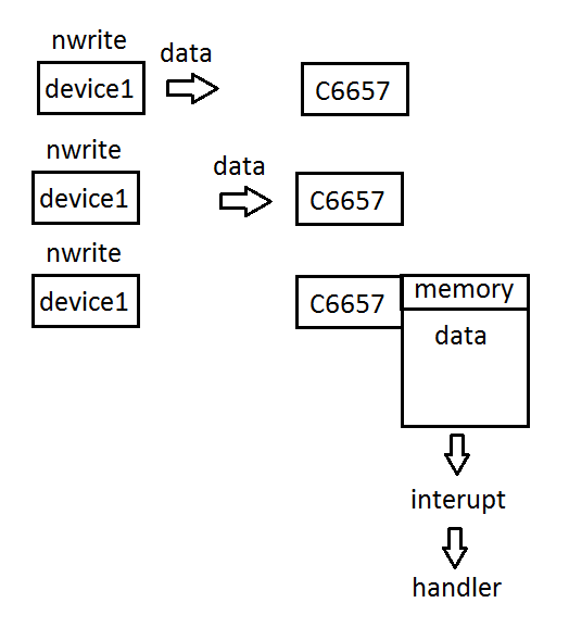
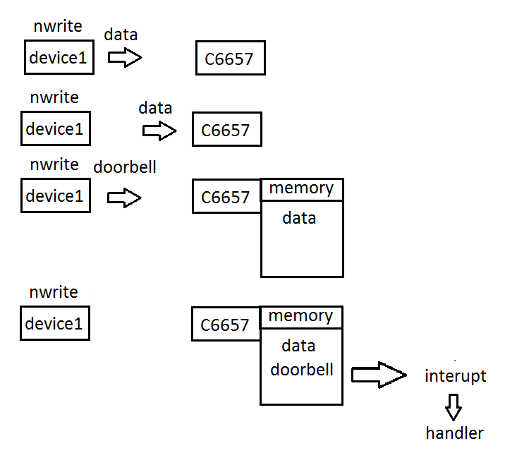
the device1 transmits to the memory С6657 at the following address 0x10800000

in C6657 only init SRIO

1) Init SRIO C6657
2) Init SRIO DEVICE1
3) creating a transmission on the device1 in C6657 at the following address memory 0x10800000 (internal memory C6657)

It works fine!

how to set interrupts C6657?? when the internal memory of the C6657 to receive a certain number of bytes ?

  • Hi,

    Already I answered the same question on your old thread.
    e2e.ti.com/.../457724

    Transfer completion interrupt is enabled on MCSDK SRIO example. Refer this example code and configure the Transfer completion interrupts on your test application.
    MCSDK Path: "C:\ti\pdk_C6657_1_1_2_6\packages\ti\drv\exampleProjects\SRIO_LoopbackDioIsrexampleproject"

    I have tested the MCSDK SRIO example project (SRIO_LoopbackDioIsrexampleproject) on my setup, the Transfer completion interrupt is triggered properly. Try to test this example on your setup. Could you please share your test code i will try to resolve the issue.?

    Thanks,
  • You did not answer my question
    the answer to my question is no example
  • you offer me I did!
    I have other problem
  • Hi,

    Have you test the MCSDK SRIO example project (SRIO_LoopbackDioIsrexampleproject) on your setup? Transfer completion interrupt is triggered properly on this example.

    Without your test code i am not able to resolve your issue. please share your test code?

    Thanks,
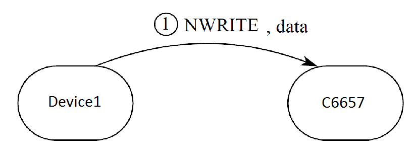
  • Ganapathi tell me the name of the type of transaction, when one device1 transmits data to the memory of another device2
    (device2 only init SRIO)

    Type 9 and 11  is unsuitable

  • Hi,

    MCSDK SRIO example project (SRIO_LoopbackDioIsrexampleproject) use the DirectIO type transfer. Have you using Type 9 / 11 message transfer?

    Take a look at below similar thread:

    Thanks,

  • I do not know what type of device1 uses!
    my task is to receive data from the device1 via C6657!
    data coming into the С6657 (I just turn SRIO on С6657) It works fine!

    to set up an interrupt me need to know the type
    I do not know what my type!!
    help me please
  • Hi,

    I am not clear for your issue. please share your test code(device1 and device2)?

    Thanks,
  • I do not have source device1 program code

    This code device2 (C6657)

    srio.c
    void Init_SRIO ()
    {
    	int I_for;
    
    	Param_SRIO_.DeviceId=0x0002;
    	Param_SRIO_.VendorId=0x0001;
    	Param_SRIO_.RevisionId=0x00000001;
    	SRIO_PowerUp();
    	
    	m_Handle = CSL_SRIO_Open (0);
    
    	CSL_SRIO_SetBootComplete(m_Handle, 0);
    
    	CSL_SRIO_GlobalEnable(m_Handle);
    	
    	CSL_SRIO_EnableBlock(m_Handle, 0);
    
    	CSL_SRIO_DisableBlock(m_Handle, 1);
    	
    	while(CSL_SRIO_IsSRIOBlockEnabled(m_Handle, 1));
    	
    	CSL_SRIO_SetLSUShadowRegs(m_Handle, 0x0, 0x0);
        for (I_for = 0; I_for < 8; I_for++)
    	{
    		CSL_SRIO_DisableSrcIDInterrupts(m_Handle, I_for);
    	}
    	CSL_SRIO_EnableBlock(m_Handle, 1);
    
    	CSL_SRIO_EnableBlock(m_Handle, 2);
    	CSL_SRIO_EnableBlock(m_Handle, 5);
    	CSL_SRIO_EnableBlock(m_Handle, 6);
    	CSL_SRIO_EnableBlock(m_Handle, 7);
    	CSL_SRIO_EnableBlock(m_Handle, 8);
    	CSL_SRIO_EnableBlock(m_Handle, 9);
    
    
    	CSL_SRIO_DisableBlock(m_Handle, 3);
    	CSL_SRIO_DisableBlock(m_Handle, 4);
    
        if (CSL_PSC_isModuleResetIsolationEnabled(CSL_PSC_LPSC_SRIO))
            CSL_PSC_disableModuleResetIsolation(CSL_PSC_LPSC_SRIO);
    
    
    		CSL_SRIO_SetNormalMode(m_Handle, 0);
    		CSL_SRIO_SetNormalMode(m_Handle, 1);
    		CSL_SRIO_SetNormalMode(m_Handle, 2);
    		CSL_SRIO_SetNormalMode(m_Handle, 3);
    
    	CSL_SRIO_EnableAutomaticPriorityPromotion(m_Handle);
    
    	CSL_SRIO_SetPrescalarSelect(m_Handle, 6);
    
        CSL_BootCfgUnlockKicker();
    
    
        //Enable PLL = 1
        //PLL multiply = 00101000 (10x)
        //VCO range = 1
        //Sleep PLL = 0
        //Loop bandwidth = 00
        //Clock Bypass = 00
        CSL_BootCfgSetSRIOSERDESConfigPLL(0x00000251);
    
        //Enable receiver = 1
        //Bus width = 010 (20 bit)
        //Operating rate = 01 (Half rate)
        //Invert polarity = 0
        //Input termination = 001
        //Symbol alignment = 01 (Comma alignment enabled)
        //Loss of signal = 000 (Disabled)
        //Clock/data recovery = 100 (First order)
        //Equalizer = 01 (Fully adaptive equalization)
        //Hold equalizer = 0
        //Enable offset compensation = 1
        //Loopback = 00 (Disabled)
        //Test patterns = 000 (Disabled)
    		CSL_BootCfgSetSRIOSERDESRxConfig(0, 0x00460495);
    		CSL_BootCfgSetSRIOSERDESRxConfig(1, 0x00460495);
    		CSL_BootCfgSetSRIOSERDESRxConfig(2, 0x00460495);
    		CSL_BootCfgSetSRIOSERDESRxConfig(3, 0x00460495);
    
        //Enable transmitter = 1
        //Bus width = 010 (20 bit)
        //Operating rate = 01 (Half rate)
        //Invert polarity = 0
        //Output swing = 0010 (870 mVdfpp)
        //Precursor Tap weight = 000
        //Adjacent post cursor Tap weight = 00000
        //Transmitter pre and post cursor FIR filter update = 1
        //Synchronization master = 1
        //Loopback = 00 (Disabled)
        //Test patterns = 000 (Disabled)
            CSL_BootCfgSetSRIOSERDESTxConfig(0, 0x00180115);
            CSL_BootCfgSetSRIOSERDESTxConfig(1, 0x00180115);
            CSL_BootCfgSetSRIOSERDESTxConfig(2, 0x00180115);
            CSL_BootCfgSetSRIOSERDESTxConfig(3, 0x00180115);
    
    
        while (1)
        {
            uint32_t    status;
    
    
            CSL_BootCfgGetSRIOSERDESStatus(&status);
    
            if (status & 0x1)
                break;
        }
    
    
        CSL_SRIO_ClearLSUPendingInterrupt(m_Handle, 0xFFFFFFFF, 0xFFFFFFFF);
    
    
        CSL_SRIO_SetDeviceInfo(m_Handle, Param_SRIO_.DeviceId, Param_SRIO_.VendorId, Param_SRIO_.RevisionId);
        CSL_SRIO_SetDeviceID(m_Handle, 0, Param_SRIO_.DeviceId, Param_SRIO_.DeviceId);
    
    
        CSL_SRIO_SetAssemblyInfo(m_Handle, SRIO_DEVICE_ASSEMBLY_ID, SRIO_DEVICE_ASSEMBLY_VENDOR_ID,
        		SRIO_DEVICE_ASSEMBLY_REVISION, SRIO_DEVICE_ASSEMBLY_INFO);
    
        /* TODO: Configure the processing element features
         *  The SRIO RL file is missing the Re-transmit Suppression Support (Bit6) field definition */
        SRIO_PE_FEATURES peFeatures;
        peFeatures.isBridge                          = 0;
        peFeatures.isEndpoint                        = 0;
        peFeatures.isProcessor                       = 1;
        peFeatures.isSwitch                          = 0;
        peFeatures.isMultiport                       = 0;
        peFeatures.isFlowArbiterationSupported       = 0;
        peFeatures.isMulticastSupported              = 0;
        peFeatures.isExtendedRouteConfigSupported    = 0;
        peFeatures.isStandardRouteConfigSupported    = 1;
        peFeatures.isFlowControlSupported            = 1;
        peFeatures.isCRFSupported                    = 0;
        peFeatures.isCTLSSupported                   = 1;
        peFeatures.isExtendedFeaturePtrValid         = 1;
        peFeatures.numAddressBitSupported            = 1;
        CSL_SRIO_SetProcessingElementFeatures(m_Handle, &peFeatures);
    
        /* Configure the source operation CAR */
        SRIO_OP_CAR opCar;
        memset ((void *) &opCar, 0, sizeof (opCar));
        opCar.portWriteOperationSupport = 1;
        opCar.atomicClearSupport        = 1;
        opCar.atomicSetSupport          = 1;
        opCar.atomicDecSupport          = 1;
        opCar.atomicIncSupport          = 1;
        opCar.atomicTestSwapSupport     = 1;
        opCar.doorbellSupport           = 1;
        opCar.dataMessageSupport        = 1;
        opCar.writeResponseSupport      = 1;
        opCar.streamWriteSupport        = 1;
        opCar.writeSupport              = 1;
        opCar.readSupport               = 1;
        opCar.dataStreamingSupport      = 1;
        CSL_SRIO_SetSourceOperationCAR(m_Handle, &opCar);
    
        /* Configure the destination operation CAR */
    	memset ((void *) &opCar, 0, sizeof (opCar));
        opCar.portWriteOperationSupport  = 1;
        opCar.doorbellSupport            = 1;
        opCar.dataMessageSupport         = 1;
        opCar.writeResponseSupport       = 1;
        opCar.streamWriteSupport         = 1;
        opCar.writeSupport               = 1;
        opCar.readSupport                = 1;
        CSL_SRIO_SetDestOperationCAR(m_Handle, &opCar);
    
        CSL_SRIO_SetDeviceIDCSR(m_Handle, Param_SRIO_.DeviceId, Param_SRIO_.DeviceId);
    
        CSL_SRIO_SetHostDeviceID(m_Handle, Param_SRIO_.DeviceId);
    
        /* Configure the component tag CSR */
        CSL_SRIO_SetCompTagCSR(m_Handle, 0x00000000);
    
     	for (I_for = 0; I_for < SRIO_MAX_NUMBER_OF_PORTS; I_for++)
    	{
    	    /* Set the PLM Port Silence Timer. */
            CSL_SRIO_SetPLMPortSilenceTimer (m_Handle, I_for, 0x2);
    
            CSL_SRIO_EnableInputPort(m_Handle, I_for);
            CSL_SRIO_EnableOutputPort(m_Handle, I_for);
    
            /* Set the PLM Port Discovery Timer. */
            CSL_SRIO_SetPLMPortDiscoveryTimer (m_Handle, I_for, 0x2);
    
           
            CSL_SRIO_SetPortWriteReceptionCapture(m_Handle, I_for, 0x0);
        }
    
        
        CSL_SRIO_SetPortLinkTimeoutCSR(m_Handle, 0x000FFF);
    
        
        //HOST = 0
        //MASTER_ENABLE = 1
        //DISCOVERED = 0
        CSL_SRIO_SetPortGeneralCSR(m_Handle, 0, 1, 0);
    
       
        CSL_SRIO_SetLLMResetControl(m_Handle, 1);
    
        /* Set the device id to be 0 for the Maintenance Port-Write operation
         * to report errors to a system host. */
        CSL_SRIO_SetPortWriteDeviceId(m_Handle, 0x0, 0x0, 0x0);
    
       
        CSL_SRIO_SetDataStreamingMTU(m_Handle, 64);
    
       
        for (I_for = 0; I_for < SRIO_MAX_NUMBER_OF_PORTS; I_for++)
            CSL_SRIO_SetPLMPortPathControlMode(m_Handle, I_for, 0);
    
        /* Set the LLM Port IP Prescalar. */
        CSL_SRIO_SetLLMPortIPPrescalar(m_Handle, 0x21);
    
       
        CSL_SRIO_SetBootComplete(m_Handle, 1);
    
      
        CSL_SRIO_EnablePeripheral(m_Handle);
    
    }
    
    char SRIO_PowerUp()
    {
    
        CSL_PSC_enablePowerDomain(CSL_PSC_PD_SRIO);
    
    
        CSL_PSC_setModuleNextState(CSL_PSC_LPSC_SRIO, PSC_MODSTATE_ENABLE);
    
    
        CSL_PSC_startStateTransition(CSL_PSC_PD_SRIO);
    
    
        while (!CSL_PSC_isStateTransitionDone(CSL_PSC_PD_SRIO));
    
     
        if ((CSL_PSC_getPowerDomainState(CSL_PSC_PD_SRIO) == PSC_PDSTATE_ON) &&
            (CSL_PSC_getModuleState(CSL_PSC_LPSC_SRIO) == PSC_MODSTATE_ENABLE))
        {
        
            return TRUE;
        }
       
        else
        {
           
            return FALSE;
        }
    }

  • an external device interface SRIO sends data to the С6657
    above my code for s6657 where turn SRIO
    good work! data receiving С6657
    how to connect the interrupt when the memory is full С6657?
    maybe so?


    SRIO_LSU_TRANSFER lsuTransfer;

    lsuTransfer.rapidIOMSB = 0;//(Uint32) pOperation->pExternalAddressMSB;
    lsuTransfer.rapidIOLSB = 0;//(Uint32) pOperation->pExternalAddressLSB;
    lsuTransfer.dspAddress = 0x0c000000;//(Uint32) pOperation->pInternalAddress;
    lsuTransfer.bytecount = 256;//pOperation->Size;
    lsuTransfer.doorbellValid = (pOperation->DoorbellRegIndex != -1);
    lsuTransfer.intrRequest = 1;
    lsuTransfer.supInt = 0;
    lsuTransfer.xambs = 0;
    lsuTransfer.priority = ((UInt8) pOperation->Priority) << 1;
    lsuTransfer.outPortID = 1;//pOperation->PortIndex;
    lsuTransfer.idSize = 0;
    lsuTransfer.srcIDMap = 0;
    lsuTransfer.dstID = pOperation->TargetId;
    lsuTransfer.ttype = 4;//(UInt8) pOperation->TransactionType;
    lsuTransfer.ftype = 2;//(UInt8) pOperation->OperationType;
    lsuTransfer.hopCount = 0;
    lsuTransfer.doorbellInfo = pOperation->DoorbellRegBits;

    CSL_SRIO_SetLSUTransfer(m_Handle, portIndex, &lsuTransfer);


    but does not work

  • Hi,

    For my understanding, you are working on devcie2 side and your device2 only receive the data from device1 via SRIO. Is it correct?

    Are you trying to configure the interrupt on device2 side, the device2 will receive the interrupt after receive the data from device1 or device2 memory is full.

    Thanks,
  • Hi
    1)For my understanding, you are working on devcie2 side and your device2 only receive the data from device1 via SRIO.
    - Yes ( This interaction is expressed in a direct memory access address of another device )

    2) Are you trying to configure the interrupt on device2 side, the device2 will receive the interrupt after receive the data from device1 or device2 memory is full. (or device2 memory is full? I mean when the memory (device2) is written a certain number of bytes)
    - essentially the same thing

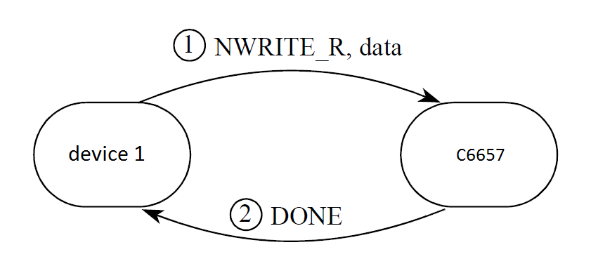
  • why do not interrupt occurs when answering DONE ( I am facing a problem with the event handler to SRIO doorbell no interrupt)

           unsigned int f_S;

       CSL_SRIO_SetDoorbellRoute(m_Handle, 1);

       for (f_S = 0; f_S < 16; f_S++)

       {

           CSL_SRIO_RouteDoorbellInterrupts(m_Handle, 0, f_S, 0);

           CSL_SRIO_RouteDoorbellInterrupts(m_Handle, 1, f_S, 0);

           CSL_SRIO_RouteDoorbellInterrupts(m_Handle, 2, f_S, 0);

           CSL_SRIO_RouteDoorbellInterrupts(m_Handle, 3, f_S, 0);

       }

       for (f_S = 0; f_S < 16; f_S++)

       {


          CSL_SRIO_DisableInterruptPacing(m_Handle, f_S);

       }

       for (f_S = 0; f_S < 32; f_S++)

       {

          CSL_SRIO_RouteLSUInterrupts(m_Handle, f_S, 0);

       }

       for (f_S = 0; f_S < 24; f_S++)

       {

          CSL_SRIO_RouteErrorInterrupts(m_Handle, f_S, 0);

       }

       m_Handle->RIO_LSU1_MODULE_ICRR = 0x00000000;

    return TRUE;

  • Hi,

    Master(Transfer) device only receive the interrupt, slave device only receive the data and send the response to master device. Based on your operation device1 only receive the doorbell interrupt, after complete the transfer. C6657 receive the data and send the response to device1.

    Thanks,
  • Hi, Thanks Ganapathi!!
    I can adjust the interrupt on the С6657 to track the number of received data ?

    or  another way

    how to track the number of received data on C6657

    or it is not possible

    another question

    in this case it is possible to track receipt of a packet on the С6657 ???


  • Hi.

    RX hardware mechanism in the peripheral that will make sure that any data transfer arrives in memory before a DOORBELL interrupt is fired. So for directIO packet types like SWRITE, where the complete transfer can be any number of packets, as long as the SWRITE packets and DOORBELL are sent on the same priority (and by the same LSU if the DSP is the TX device) such that there is no reordering, the payloads will have landed in memory before the interrupt is fired.

    DOORBELLs can be used for generic interrupt purposes. Since they are generic and their use is defined by the application, there is no reference to MAU or any specific data transfer. The use of DOORBELLs for the interrupt in your scenario is the best way to handle it. If the length of transfer is not agreed upon by TX and RX device in the system and the RX device needs to determine the total payload size, then you can do things such as send the total byte count in the payload of the message (first word for example, like a customer header), or if there are finite number of payload sizes, you could use the particular DOORBELL interrupt source to indicate (For example DOORBELL bit 1= 256B tranfer interrupt).

    Thanks,
  • Thanks you

    I will try to adjust the interrupt on the С6657  for this circuit

    glist

  • I read all datasheet. Unfortunately for my case (diagram above) does not describe how to configure Interrupt C6657.
    the C6657 is processing data, how the C6657 recognizes that the new data came from the device1

    Prompt me please

  • Hi,

    For enabling transfer completion interrupts for DIO transactions (NWRITE, NWRITE_R and NREAD). The following bit needs to be set, while setting up the LSU registers:

    LSU_REG4.Interrupt Req = '1'

    A better approach here is to configure the LSU registers to automatically send a doorbell to the external PE on the completion of the DIO transaction and setting up a transfer completion interrupt for the same. This can be done by setting up the following:

    LSU_REG3.Drbll_val = '1'

    LSU_REG4.Interrupt Req = '1'

    LSU_REG5.Drbll Info = "Doorbell info" (The doorbell interrupt expected by the external PE)

    For more information, please refer to section 2.3.2 "Direct I/O Operation" in the SRIO users guide. Doorbell interrupt is implemented on attached SRIO example project(in 2DSP test mode), take a look at this example to understand the interrupt configuration. Also refer the attached SRIO programming guide.

    8461.KeyStone_SRIO.zip

    5661.SRIO_Programming_Performance.pdf

    Thanks,

  • Hi
    I want to clarify just in case
    I do not want to adjust the interrupt on the device1
    I use only NWRITE on device1.

    on C6657 adjust LSU_REG4.Interrupt Req = '1'
    and on C6657 srio will generate an interrupt each time the new data comes from the device1 ?
  • LSU_REG4.Interrupt Req = '1'  Configure outgoing port ID, Priority and other RIO parameters. */ This setting device1

    I use on device1 only NWRITE 

    register LSU_REG4.Interrupt Req = '1'

     Configure outgoing an interrupt at the end of transmission for Device1


    I need to interrupt an incoming с6657

    help me nucu

  • how to adjust the interrupt data is received

  • Hi,

    C6657 srio will not generate/get an interrupt each time the new data comes from the device1. The transfer control interrupt and doorbell interrupts are not support your requirement. Better to use the EDMA for SRIO transfer.

    Please take a look at below similar treads. You can always search the E2E forums to see if others in the past or currently have the same issues you are working on.

    Thanks,

  • I read the article is not an answer to my question. I have a lot of questions . for example
    If C6657 srio will not generate/get an interrupt each time the new data comes from the device1.
    if it is connected via the interrupt edma3, too, will not be interrupted ?
    Examples for my case there are no? or approximately how many years can appear examples?
  • Hi,

    Through EDMA, it can be interrupted, which is feasible. For more info. on the same, kindly walkthrough the EDMA3 video training material available below by Eric Wilbur and Scott Specker and please check part no 14 and 15 in the video series "Using C6000 EDMA3 - Part 2 (14 of 15)" and "Using C6000 EDMA3 - Part 2 (15 of 15)"

    training.ti.com/using-c6000-edma3-part-2-14-15

    Thanks & regards,
    Sivaraj K