This thread has been locked.

If you have a related question, please click the "Ask a related question" button in the top right corner. The newly created question will be automatically linked to this question.

DM355 color is missing in video output

Several of our custom boards have problems with video output. Have not seen that before. They run exact same code and TVOUT (composite video output) outputs black-and-white image. Exact same code on the good board produces color. In an attempt to eliminate any fault in our code we enabled the color bars (bit 8 in VDPRO register of VPBE). Same result, good boards have colored bars. "Bad" boards have have grayscale bars.

What could cause the problem? What could cause the color to disappear? Is that a faulty chip?

Here is the B&W (bad):

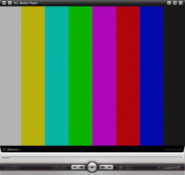
Here is color (good):

  • Do you get the same result on different TVs?

    Check that the stability and frequency of the system oscillator is correct.

    Most likely this is caused by fluctuations/jitter/errors in the reference clock causing the color sub-carrier frequency to be wrong/unstable. This in turn can cause the TV/monitor to believe that the color carrier is bad and switch to monochrome.

    Can you also capture the TV out signal on an oscilloscope (whilst still plugged in to the TV). I need to see a line of about 100us in duration.

    BR,

    Steve

  • We used a TV and also a little "Composite-to-USB" capture device (this device + VLC is what I used to get the TV screen shots). Both had consistent results. Overall the board seems to be working fine. I will capture the signal and post it here.

  • Are there any other output clocks from the DM355 available for measuring that are derived from the same reference crystal as the clock used for the video encoder? If so are you able to check the frequency with a frequency counter (note, an oscilloscope is not accurate enough to do this). Any variation from the expected output of the measured clock will be the same percentage error as the encoder clock.

    Variations in crystal frequency are usually caused by the load capacitors not being tuned to the PCB parasitic capacitances, causing the nominal crystal frequency to be incorrect (and potentially also reducing the margin for stable oscillations to be reduced [there is an oxymoron if there ever was one!!!])

    BR,

    Steve

  • We use a 24MHz clock from CLKOUT1 to drive the image sensor. I measured that frequency at it was 240007xx Hz (xx is because I don't remember the exact digits). That is 0.0029%. A good board measured 240004xx Hz (0.0017%).

    Here is the video signal (one line) of color bars taken on one of the "bad" boards.

    Good board looks exactly the same.

    I have looked closer at the "colorburst" at the beginning of the line and both looked exactly the same:

    Any other ideas?

  • Bingo! You were spot on.

    Upon closer inspection the load capacitor on input side MXI1 had cold solder. Soldering that cap made the color appear.

  • Fantastic. Glad you are up and running now.


    BR,

    Steve