This thread has been locked.

If you have a related question, please click the "Ask a related question" button in the top right corner. The newly created question will be automatically linked to this question.

AM3874 SCR register

Other Parts Discussed in Thread: AM3874, SYSCONFIG

Hi,

I have one question regarding SCR register of UART for AM3874.

In SCR register, Bit3(TXEMPTYCTLIT), this bit "0" shows Normal mode ofr THR interrupt. And "1" shows THR interrpt is generated when TX FIFO and TX shift register are empty.

I don't know what is "Normal mode" (bit3="0"). I think bit3="1" is normal mode. Because THR interrupt is generated when TX FIFO is empty. But when bit3="0" is "Normal mode". What is this normal mode?

Please let me know.

Best regards,

Michi

  • Michi,

    I will have a look on your questions and provide you me feedback when I have something.

    Regards,
    Pavel

  • Michi Yama said:
    In SCR register, Bit3(TXEMPTYCTLIT), this bit "0" shows Normal mode ofr THR interrupt. And "1" shows THR interrpt is generated when TX FIFO and TX shift register are empty.

    Normally THR interrupt is generated when there is enough space in the transmit FIFO for a write burst (configured via TLR and FCR), which is always sooner than FIFO empty since the max write burst configurable (63) is less than the FIFO size (64).

    If the FIFO is disabled, then means THR interrupt is generated when it is possible to write a byte.  This basically behaves as if both FIFO size and write burst length are 1 byte.  In this case THR interrupt does mean "FIFO empty", but it still doesn't mean the transmitter is empty.

    In other words, when TXEMPTYCTLIT=0 you get an interrupt when you can write more data to the UART.  When TXEMPTYCTLIT=1 you get an interrupt when the UART is completely done transmitting.  Effectively it gives you an interrupt-based alternative to polling bit 6 of the LSR.

  • Dear Matthijs-san,

    Thank you for your kindly explanation.

    May I have one more question?

    As you know, regarding UART module, there are some write only registers, such as THR, FCR.

    Are these write only registers assigned to other address? If possible, I would like to confirm the

    contents of the write only registers. 

    I appreciate your quick reply.

    Best regards,

    Michi

  • Please be aware that registers cannot always be treated like memory.  In general, a read or write of a register should be considered a function call to the peripheral.  Quite often these will be the getter and setter of some actual value, but not always.  A write to THR for example pushes a byte onto the transmit FIFO, so it doesn't really have a "value" as such.  A read from the same location (RHR) pulls a byte from the receive FIFO, and beware that several other registers (IIR, LSR, MSR) have side-effects when you read them and therefore cannot safely be "checked" without affecting the state of the UART.

    FCR is a mixed bag and its relevance depends also on SCR.  Bit 0 (fifo enabled) can be read via IIR (bits 6 and 7), but reading IIR isn't quite safe since some events are reported only once.  If the FIFO is disabled then the rest of FCR is irrelevant, but you'll almost certainly want to have the FIFO enabled.  Note that this is supposed to be done during initialization before the UART it put into operational mode, so you can read IIR without worry at that time if you wish. You're not allowed to enable or disable the FIFO while the UART is in use (but beware that the UART doesn't prevent you from doing so).

    The relevance of the rest of FCR also depends on other registers. I strongly suggest:

    • Setting bit 0 (DMAMODECTL) of SCR to 1; this means the DMA mode is configured via SCR bits 1-2 instead of via FCR.  This is more flexible and you can verify the contents of SCR at any time.
    • Leaving bits 6-7 (TX/RXTRIGGRANU1) at 0 and programming nonzero read and write burst sizes (in words) in TLR.

    With this combination of settings, bits 3-7 of FCR are ignored so there's no need to read them.  FCR can now be viewed purely as a command register:  write 3 to clear the rx fifo, write 5 to clear the tx fifo, write 7 to clear both fifos.  Also write 7 at least once during initialization.

    There is, as far as I know, no actual way to read back bits 3-7 of FCR so if for some reason you really need the ability to set the write/read burst size in bytes rather than in words (by setting SCR bits 6/7 and programming TX/RX_FIFO_TRIG in FCR) then my suggestion would be: whenever you write FCR, write the same value to the SPARE register.  Then at least you have a fixed place to check for the last value you wrote to FCR.

    FYI, my suggested initialization procedure for interrupt (or polling) mode is:

    • reset uart via SYSC.SOFTRESET and poll SYSS.RESETDONE for completion
    • set power management options in SYSC as desired
    • LCR = 0xbf  // extended config mode
    • EFR = 0x10 combined with flow control and/or char detect options you desire.  Also configure XON/XOFF regs here if needed.
    • LCR = 0x80  // normal config mode
    • SCR = 0x01  // no DMA
    • MCR = 0x40  // enter fifo config
    • configure read/write burst sizes in TLR
    • configure trigger levels in TCR if using rx flow control
    • MCR = 0x00  // exit fifo config
    • FCR = 0x07  // reset and enable FIFOs
    • DLL = 0x1a  // example for 115200
    • LCR = 0x03  // example for 8N1
    • MDR1 = 0x00  // enable UART
    • wait briefly (1 μs is plenty) and reset FIFOs again (FCR = 0x07) in case omap4 erratum i202 also applies to the centaurus uart... just to be on the safe side; never hurts
    • enable interrupts as desired

    unlike the TRM I actually advise against clearing EFR.4 since the access it enables is also useful while the uart is in use, and EFR cannot be accessed to change it while the uart is in use

  • Dear Mathijs-san,

    I have one more question.

    Regarding IT_PENDING bit of IIR register, as to my knowledge,  when this bit is "0" (with IT_TYPE -THR interrupt), TXFIFOE bit of LSR register is "1" (Tx interrupt is generated.). Is my understanding right?

    Now my customer has one issue. The issue is that IT_PENDING bit is not set. Its bit is always cleared ("0": an interrupt is pending).This bit should be set  by MCU writes the data to TX FIFO?

    Please advise me.

    Best regards,

    Michi

  • Oh, and just for the record: I personally think the UART's register interface is by far the most bizarre contraptions I've seen so far on this chip, and backwards compatibility with some ancient UART really isn't a valid excuse for this steaming pile of crap. This thing is just an act of cruelty towards programmers.

    If it's any comfort, TI's programmers also got lost in it: the initialization procedure given in the TRM clears EFR.4 while MCR.6 is still set.  I already mentioned that clearing EFR.4 is a bad idea in my opinion, and this is nicely illustrated by the fact that it renders MCR.6 read-only, so the subsequent attempt to clear it fails.  This means the procedure fails at its stated objective of removing access to the FIFO config registers, and also leaves the UART in a state where you can't access MSR (the modem status register).  Fortunately the bit is not only readonly but also ignored when EFR.4 is cleared, so the attempt to clear it is pointless and fails, but this has less consequences than I originally thought.

  • The TX irq indicates that the uart TX FIFO is ready to receive a burst of data.  If you have no data to send then you don't care about that, therefore you should disable the TX irq until you do have data to send.

  • Dear Matthijs-san,

    Thank you for your support.

    I need more your support. How do you think the following situation?

    ---------

    The UART registers setting :

    TLR=0x81, SCR=0xC0, FCR=0x01

    From the above register value, threshold level (TLR[3:0]=1) is "1 byte". And then, the host writes 8 bytes data to TxFIFO at a time. THR interrupt is generated when remaining data of TX FIFO is one byte because threshold level is "1byte". This means "IT_PENDING" bit is always "0" (An interrupt is pending). 

    After for while, TxFIFO becomes full. It can be confirmed by TXFIFOFULL of SSR register. But IT_PENDING" bit of IIR register is still "0". I think this bit should be set when the data of TxFIFO is over two bytes. But this bit is not set when reached TxFIFO to full.

    Why IT_PENDING bit is not set? Please give me your advice.

    I appreciate your quick reply.

    Best regards,

    Michi


  • Michi Yama said:

    TLR=0x81, SCR=0xC0, FCR=0x01

    From the above register value, threshold level (TLR[3:0]=1) is "1 byte"

    No, if setting the read/write burst length (I think those are clearer names... especially since there are three other "thresholds"/"trigger levels" already) with byte-granularity is required, then each is a 6-bit value split into two parts.  The number of words is still in TLR, while the number of "leftover" bytes is programmed via FCR.  Verbose example:

    // preferred amount of data read/written at once.
    // must be nonzero and less than fifo size (64)
    unsigned const read_burst  = 1;
    unsigned const write_burst = 8;
    
    unsigned const dma_mode = 0;  // no dma
    
    // assuming EFR.4 and MCR.6 are set at this point, and LCR != 0xbf
    
    uart->scr = 0
            | 1 << 0        // disable legacy mode of configuring dma mode via FCR
            | dma_mode << 1 // configure dma mode here instead
            | 1 << 6        // allow write_burst to be configured in bytes
            | 1 << 7        // allow read_burst to be configured in bytes
            ;
    uart->tlr = 0
            | (write_burst >> 2) << 0   // words per write burst
            | (read_burst  >> 2) << 4   // words per read burst
            ;
    uart->fcr = 0
            | 1 << 0                    // fifo enabled
            | 1 << 1                    // reset rx fifo
            | 1 << 2                    // reset tx fifo
            | (write_burst & 3) << 4    // leftover bytes per write burst
            | (read_burst & 3) << 6     // leftover bytes per read burst
            ;

    Note that setting read_burst to 1 is only appropriate if you need the lowest latency possible for every character. If you use higher values you will still get all data but slightly delayed to batch them together.  The benefit is that you get fewer interrupts overall, and if you get an "rx" event (rather than "rxto") you know you can blindly read at least a full burst of data any further checking of IIR or LSR.   If data is received but not enough for a complete burst, the uart will wait 4 character times for additional data, but if none arrives it'll send an "rxto" event so you can read read the remaining bytes in the FIFO.

    Same with write burst: a tx event means you can write a full burst without any further checking, but you're certainly also allowed to write less.  (This is different for DMA btw, there the burst sizes are exact.)

  • To clarify: using byte-granularity for bursts does imply that you can't reset the FIFOs without overwriting (bits 0 and 1 of) the read/write burst lengths, which is an inconvenience but probably a minor one.

    Also, the documentation isn't entirely clear on this but as far as I can tell (and a quick test seems to confirm it), it's okay to change TLR and TCR while the uart is in operation, so if desired you could use small burst size for low latency and switch to large burst size for bulk transfer.

  • Dear Mathijs-san,

    Thank you for your quick reply.

    Unfortunately, I don't know your advice well. You said the initialization of UART is wrong,doesn't it?

    If it is so, could you check the my source code for intialization? I will attach it.

    6886.UART_source.txt
    //------------------------------------------------------------------------------
    //
    //  Function:  InitializeUART
    //
    //  This function initializes a UART register.
    //
    static VOID InitializeUART(UARTPDD *pPdd)
    {
        SOC_UART_REGS *pUartRegs = pPdd->pUartRegs;
    
        // Reset UART & wait until it completes
        OUTREG8(&pUartRegs->SYSC, UART_SYSC_RST);
        while ((INREG8(&pUartRegs->SYSS) & UART_SYSS_RST_DONE) == 0);
    
        // Enable wakeup
        // REG: turning off Auto Idle and turning on Smart Idle
        OUTREG8(
        &pUartRegs->SYSC,
        // Try turn on force idle, smart idle or turn on no idle
        // Lets configure force idle here we will change this in HWopen.
        UART_SYSC_IDLE_FORCE|UART_SYSC_WAKEUP_ENABLE|UART_SYSC_AUTOIDLE
        );
    
        // Ensure baud rate generator is off
        OUTREG8(&pUartRegs->LCR, UART_LCR_DLAB);
        OUTREG8(&pUartRegs->DLL, 0);
        OUTREG8(&pUartRegs->DLH, 0);
    
        // Select UART mode
        OUTREG8(&pUartRegs->MDR1, UART_MDR1_UART16);
    
    
        // Line control: configuration mode B
        OUTREG8(&pUartRegs->LCR, UART_LCR_MODE_CONFIG_B);
        // Enable access to IER bits 4-7, FCR bits 4-5 and MCR bits 5-7
        SETREG8(&pUartRegs->EFR, UART_EFR_ENHANCED_EN);
    
        // Line control: operational mode
        OUTREG8(&pUartRegs->LCR, UART_LCR_MODE_OPERATIONAL);
    
        // Enable sleep mode
        // Do not enable sleep mode hardware flow control will have problem
       // OUTREG8(&pUartRegs->IER, UART_IER_SLEEP_MODE);
    
        // Enable access to TCR and TLR
        SETREG8(&pUartRegs->MCR, UART_MCR_TCR_TLR);
        // Start receive when 32 bytes in FIFO, halt when 60 byte in FIFO
        OUTREG8(
            &pUartRegs->TCR,
            UART_TCR_RX_FIFO_TRIG_START_24|UART_TCR_RX_FIFO_TRIG_HALT_40
            );
    
        // This will create a space of 60 bytes in the FIFO for TX
        // Later we set FCR[4:5] so that the space is 63 bytes
        // we adjusted the TX DMA frame size to be 63 so we don't overrun our 
    fifo
        if(pPdd->RxDmaInfo)
        {
            // if RxDMA is enabled, set up the MSBs of RX_FIFO_TRIG according
            // to the value in pPdd->dwRxFifoTriggerLevel
            BYTE    bRxTrigDMA = (BYTE)((pPdd->dwRxFifoTriggerLevel >> 2) << 4);
    
            OUTREG8(&pUartRegs->TLR, UART_TLR_TX_FIFO_TRIG_DMA_0 | bRxTrigDMA);
        }
        else
        {
    //        OUTREG8(&pUartRegs->TLR, UART_TLR_TX_FIFO_TRIG_DMA_0);
            OUTREG8(&pUartRegs->TLR, (UCHAR)pPdd->dwTxBufIntr); //�@dwTxBufIntr=0x81
        }
    
        // Disable access to TCR and TLR
        CLRREG8(&pUartRegs->MCR, UART_MCR_TCR_TLR);
    
        pPdd->CurrentSCR = UART_SCR_TX_TRIG_GRANU1 | UART_SCR_RX_TRIG_GRANU1;
        pPdd->CurrentFCR = 0;
    
        if(pPdd->RxDmaInfo || pPdd->TxDmaInfo)
        {
            //pPdd->CurrentSCR |= UART_SCR_DMA_MODE_CTL;
            pPdd->CurrentSCR |=
                                UART_SCR_DMA_MODE_CTL |
                                UART_SCR_DMA_MODE_2_MODE1 |
                                UART_SCR_TX_EMPTY_CTL;
            pPdd->CurrentFCR |= UART_FCR_DMA_MODE;
        }
    
        OUTREG8(&pPdd->pUartRegs->SCR, pPdd->CurrentSCR);
    
        pPdd->intrMask = UART_IER_RHR;
        pPdd->CurrentFCR |= UART_FCR_FIFO_EN;  
    
        if (pPdd->RxDmaInfo == NULL)
        {
            pPdd->CurrentFCR |= UART_FCR_RX_FIFO_TRIG_8;
        }
        else
        {
            // if RxDMA is enabled, set up the LSBs of RX_FIFO_TRG according
            // to the value in pPdd->dwRxFifoTriggerLevel
            pPdd->CurrentFCR |= ((pPdd->dwRxFifoTriggerLevel & 0x03) << 6);
        }
    
        OUTREG8(&pUartRegs->FCR, pPdd->CurrentFCR);
    
        // Line control: configuration mode B
        OUTREG8(&pUartRegs->LCR, UART_LCR_MODE_CONFIG_B);
        // Disable access to IER bits 4-7, FCR bits 4-5 and MCR bits 5-7
        CLRREG8(&pUartRegs->EFR, UART_EFR_ENHANCED_EN);
        // Line control: operational mode
        OUTREG8(&pUartRegs->LCR, UART_LCR_MODE_OPERATIONAL);
    
        // Set default LCR 8 bits, 1 stop, no parity
        SETREG8(&pUartRegs->LCR, UART_LCR_CHAR_LENGTH_8BIT);
    }


    I would like to know why IT_PENDING bit of IIR register does not become to "1" when TxFIFO is full.

    Could you advise me again?

    I appreciate your kindly support.

    Best regards,

    Michi

  • I'm afraid I've spotted various problems in your initialization code.  The more serious one is that you don't seem to be programming the baudrate anywhere!  Various other points are:

    • Unless you have specific reason to do otherwise, sysconfig.idlemode should be "auto" (2) or "auto with wakeup" (3).  The never-idle and force-idle options are meant for debugging or working around problems.
    • The "ensure baud rate generator off" paragraph of code is pointless since you just reset the entire peripheral already.
    • Configuring MDR1 should be the last step of initialization, not the first
    • As I mentioned before, I advise against clearing UART_EFR_ENHANCED_EN (done in your code near the bottom), since this has no beneficial purpose and it makes various features inaccessible.

    I would still strongly suggest following the initialization outline I gave in my second post in this topic, modified to support setting read/write burst length with byte granularity as I explained above.

    As for your original question:

    Michi Yama said:

    I would like to know why IT_PENDING bit of IIR register does not become to "1" when TxFIFO is full.

    There are many reasons why IT_PENDING can be 0, you need to inspect the remainder of IIR for that and in some cases also other registers, depending on which interrupt sources you enabled.  However, whether the TxFIFO is full or not has no direct relevance to IIR: the tx irq goes away when you disable it or when the TxFIFO is almost full, more specifically when the remaining space left is less than the write burst size you configured in TLR (and optionally FCR).

    Note that many registers have info about the Tx FIFO:  Whether or not the Tx FIFO is full can be examined in SSR bit 0, but there is no irq associated with this.  When there's enough space in the FIFO for a write burst and the tx irq is enabled via IER, you will get an irq for this via IIR, but this will typically be somewhere in between empty and full.  Whether the Tx FIFO is empty can be examined in LSR bit 5 or ISR2, and IER2 can give an irq on this (which doesn't show up in IIR at all).  Finally, whether the Tx FIFO and serializer are empty (transmit side fully idle) can be found in LSR bit 6, and an irq can be obtained by setting SCR bit 3; which then replaces the normal tx irq.

    The exact amount of data in the two FIFOs can also at any time be examined in registers which, I just noticed to my surprise, are undocumented in the DM814x/AM387x TRM.  The register at offset 0x64 contains the current number of bytes in the Rx FIFO and the next one at 0x68 contains the number of bytes in the Tx FIFO.

    Hope this helps,

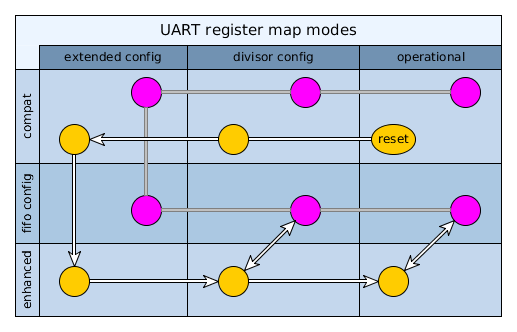
  • I don't know if it will help to clarify or confuse even more, but I made a diagram of all modes of the UART's register interface (I'm ignoring all infrared-stuff):

    The columns represent LCR == 0xBF, LCR == 0x80, LCR < 0x80 respectively.  The color of the state indicates whether MCR.6 is set (purple) or clear (yellow).  All nine squares grant different access to registers, except that "compat" is just a restricted version of "enhanced".  My suggested route is given by the white arrows.  The grey lines are the remaining possible transitions.

    While in extended config (LCR == 0xBF), one can set EFR.4 to move down from compatibility-mode to enhanced mode.  Then, after exiting extended config to regain access to MCR you can set MCR.6 to access the fifo config (TLR and TCR).  In operational mode you will normally have it cleared to be able to access MSR, but you can briefly reenter fifo config mode to adjust the thresholds on the fly (this is permitted as far as I know).

    The init procedure in the TRM actually climbs back into compat mode for no good reason, and it does so while MCR.6 is set.  It tries to clear it later but as the diagram shows, no such transition exists (MCR.6 is readonly and non-functional in compatibility-mode), so it ends in the topright purple state.  No access to fifo config or enhanced functionality is possible in this state.

    Various states in this diagram need to be visited to perform various parts of UART initialization:  SCR and SYSC can be configured basically at any time.  Flow control is configured in extended config (except for the xon-any bit which is in enhanced-mode MCR).  The FIFOs are configured in fifo config mode and by writing to FCR (accessible when not in extended config) to reset and enable them (and for the bottom bits of read/write burst size).  The bitrate can configured at any time before entering operational state.

    Now finally, operational state is entered by writing the desired frame format into LCR.  Once in this state, IER is accessible to enable/disable interrupts as desired, but this can also be done after the UART has been enabled.  With all settings done, the final step is to enable the uart functional logic by setting MDR1.MODE_SELECT.

    The UART should now be working, however in case issue "i202" mentioned in the errata of both the omap4 and omap5 also affects the DM814x, it seems wise to follow its workaround procedure: wait briefly ("5 interface clock cycles + 5 functional clock cycles"; that's about 155 ns) and reset the FIFOs again.

  • Dear Matthijs-san,

    Thank you very much for your kindly support. I really appreciate your help.

    According to the latest information from customer, this issue never happened when customer does not use the threshold level of TxFIFO. If THR interrupt codition that the interrupt is issued when TxFIFO empty condtion, THR interrupt is issued when TxFIFO is empty only.

    However, if the threshold level of TxFIFO is configured to "one byte", THR interrupt is nevr deasserted when characters in the TxFIFO reach to the threshold level.

    Now I am trying to reproduce this issue on TI's EVM. But I don't do this yet. The uart test code of EVM does not work well with my EVM. If you have some UART code working with AM3874, could you supply it to me?

    Best regards,

    Michi

  • Ah, that's a much clearer description of the problem.  I'm not seeing this issue however with these steps:

    I configured the write burst size to 1 byte:  SCR[6] = 1, TLR[0..3] = 0b0000, FCR[4..5] = 0b01
    I enabled the tx irq:  IER[1] = 1
    I used flow control to block transmission to ensure the FIFO could fill up
    I executed a loop which verified IIR indicated a Tx irq, transmitter a byte, repeated until IIR no longer indicated Tx irq or more than 64 were transmitted.  The first condition terminated the loop: exactly 64 bytes could be written, after which IIR indicated no irq pending.

  • I did another test: serial port configured at a low rate (9600 bits/s).  I performed a similar loop as above, but simply transmitting a large buffer of data. I also added a read of SSR right after the last byte-write.  All data arrived intact (showing no tx irqs were given without space in the fifo) and SSR[0] was set, indicating the transmit FIFO was full at that time (showing no space in the fifo was left without giving a tx irq)

    As far as I can tell, the transmit irq works correctly.

    (Although you haven't mentioned any use of DMA, and use thereof would obviously change things substantially compared to interrupt-driven use, I do feel it's worth mentioning there is a known issue with transmit DMA events.  It is mentioned in the errata and has easy workaround of configuring a custom dma tx event threshold of 63-writeburst, overriding the default of 64-writeburst.)

    Update: at low speeds, whether or not hardware handshake is enabled is completely irrelevant of course since both sides can keep up easily, so I removed that.

  • Dear Matthijs-san,

    Thank you for your continuous support.

    Regarding UART errata, customer does not use the DMA for data transfer. So I think UART errata is not applied to the customer issue.

    Do you have any idea for this issue?

    I appreciate your kindly support.

    Best regards,

    Michi

  • As far as I can tell, the uart's behaviour with regard to the FIFO thresholds behaves as expected.  In my experience, it even responds correctly if you change the thresholds on-the-fly while a data transfer is in progress; the interrupt status instantly changes to reflect the new settings.  I have not encountered any problem under diverse circumstances.  Without a more specific test case I'm therefore not sure how I can help...

    1. Again check the initialization closely, since this is probably the most complicated and error-prone part of interacting with the uart, and this thread has accumulated a lot of information on it.  For reference, for my tests I used the following sequence and minor variations thereof:

    • SYSC = 0x11;  // default power management
    • LCR = 0xBF;  // extended config
    • EFR = 0x10;  // enhanced mode, no flow control
    • LCR = 0x80;  // normal config
    • SCR = 0xC1;  // no DMA, byte-granular read/write bursts
    • MCR = 0x40;  // enter fifo config
    • TLR = 0x00;  // read/write burst are 0 words...
    • FCR = 0x57;  // ... and 1 byte each, reset and enable FIFOs
    • MCR = 0x00;  // exit fifo config (optional)
    • DLH = 0x01; DLL = 0x39;  // 9600 baud
    • LCR = 0x03;  // operational mode, 8N1
    • MDR1 = 0x00;  // enable UART
    • (brief delay)
    • FCR = 0x57;  // reset FIFOs again
    • IER = 0x02;  // enable Tx irq

    You can omit the "exit fifo config" step if you don't care about access to MSR and prefer to keep access to TLR and TCR.  Using a low bitrate makes it easier to test-code to observe the dynamic behaviour of the FIFO, but I've used high bitrates also (in which case flow control can be useful for testing).

    2. Try to narrow down the problem to a simple test case.  Also, as I mentioned earlier there are registers which give the current amount of data in both FIFOs, they may be useful for diagnostic purposes (but inexplicably are undocumented in the DM814x/AM387x TRM, although they are documented in TRMs of related processors).

    3. If more irqs are enabled than just the transmit irq, be sure the interrupt status is interpreted right.  Given the full set of interrupt sources (and how to deal with them correctly) is also quite complex I may post something on that later, but until the problem is I suggest avoiding enabling any more interrupts than absolutely necessary for testing purposes.

  • Dear Matthijs-san,

    Thank you for your kindly support.

    Now I am editing to reproduce the issue with AM3874 EVM by using AM335x StarterWare.

    The attached file is the uartEcho source of StarterWare.

    5037.uartEcho.c
    /**
     * \file   uartEcho.c
     *
     * \brief  This example application demonstrates the working of UART for serial
     *         communication with another device/host by echoing back the data
     *         entered from serial console.
     *      
     *         Application Configuration:
     *       
     *          Modules Used:
     *              UART0
     *              Interrupt Controller
     *
     *          Configurable Parameters
     *              None
     *              
     *          Hard-coded configuration of other parameters:
     *              1) Baud Rate - 115200 bps
     *              2) Word Length - 8 bits
     *              3) Parity - None
     *              4) Stop Bits - 1
     *              5) FIFO Threshold Levels:
     *                 a) TX Trigger Space value - 56
     *                 b) TX Threshold Level - 8 (TX FIFO Size - TX Trigger Space)
     *                 c) RX Threshold Level - 1
     *
     *         Application Use case:
     *             1) Application demonstrates the Receive/Transmit features
     *                of UART using a FIFO.
     *             2) Interrupt features related to FIFO trigger levels are
     *                demonstrated for reading/writing from/to the FIFO.
     *
     *      Running the Example:
     *          On executing the example:
     *          1) A string is displayed on the serial console of the host machine.
     *          2) The user is then expected to key in data on the serial console.
     *             The keyed in data are immediately echoed back by the application
     *             and are visible on the serial console.
     *
     */
    
    /*
    * Copyright (C) 2010 Texas Instruments Incorporated - http://www.ti.com/ 
    */
    /* 
    *  Redistribution and use in source and binary forms, with or without 
    *  modification, are permitted provided that the following conditions 
    *  are met:
    *
    *    Redistributions of source code must retain the above copyright 
    *    notice, this list of conditions and the following disclaimer.
    *
    *    Redistributions in binary form must reproduce the above copyright
    *    notice, this list of conditions and the following disclaimer in the 
    *    documentation and/or other materials provided with the   
    *    distribution.
    *
    *    Neither the name of Texas Instruments Incorporated nor the names of
    *    its contributors may be used to endorse or promote products derived
    *    from this software without specific prior written permission.
    *
    *  THIS SOFTWARE IS PROVIDED BY THE COPYRIGHT HOLDERS AND CONTRIBUTORS 
    *  "AS IS" AND ANY EXPRESS OR IMPLIED WARRANTIES, INCLUDING, BUT NOT 
    *  LIMITED TO, THE IMPLIED WARRANTIES OF MERCHANTABILITY AND FITNESS FOR
    *  A PARTICULAR PURPOSE ARE DISCLAIMED. IN NO EVENT SHALL THE COPYRIGHT 
    *  OWNER OR CONTRIBUTORS BE LIABLE FOR ANY DIRECT, INDIRECT, INCIDENTAL, 
    *  SPECIAL, EXEMPLARY, OR CONSEQUENTIAL DAMAGES (INCLUDING, BUT NOT 
    *  LIMITED TO, PROCUREMENT OF SUBSTITUTE GOODS OR SERVICES; LOSS OF USE,
    *  DATA, OR PROFITS; OR BUSINESS INTERRUPTION) HOWEVER CAUSED AND ON ANY
    *  THEORY OF LIABILITY, WHETHER IN CONTRACT, STRICT LIABILITY, OR TORT 
    *  (INCLUDING NEGLIGENCE OR OTHERWISE) ARISING IN ANY WAY OUT OF THE USE 
    *  OF THIS SOFTWARE, EVEN IF ADVISED OF THE POSSIBILITY OF SUCH DAMAGE.
    *
    */
    
    #include "uart_irda_cir.h"
    #include "soc_AM335x.h"
    #include "interrupt.h"
    #include "evmAM335x.h"
    #include "hw_types.h"
    #include "consoleUtils.h"
    
    /******************************************************************************
    **              INTERNAL MACRO DEFINITIONS
    ******************************************************************************/
    #define BAUD_RATE_115200          (115200)
    #define UART_MODULE_INPUT_CLK     (48000000)
    
    /*
    ** The number of data bytes to be transmitted to Transmit FIFO of UART
    ** per generation of the Transmit Empty interrupt. This can take a maximum
    ** value of TX Trigger Space which is 'TX FIFO size - TX Threshold Level'.
    */
    #define NUM_TX_BYTES_PER_TRANS    (56)
    
    /******************************************************************************
    **              INTERNAL FUNCTION PROTOTYPES
    ******************************************************************************/
    static void UartInterruptEnable(void);
    static void UART0AINTCConfigure(void);
    static void UartFIFOConfigure(void);
    static void UartBaudRateSet(void);
    static void UARTIsr(void);
    
    /******************************************************************************
    **              GLOBAL VARIABLE DEFINITIONS
    ******************************************************************************/
    
    /* A string to be transmitted by UART. */
    unsigned char txArray[] = "StarterWare AM335X UART Interrupt application\r\n";
    
    /* A flag used to signify the application to transmit data to UART TX FIFO. */
    unsigned int txEmptyFlag = FALSE;
    
    /*
    ** A variable which holds the number of bytes of the data block transmitted to
    ** UART TX FIFO until the current instant.
    */
    unsigned int currNumTxBytes = 0;
    
    /******************************************************************************
    **              FUNCTION DEFINITIONS
    ******************************************************************************/
    
    int main()
    {
        unsigned int numByteChunks = 0;
        unsigned int remainBytes = 0;
        unsigned int bIndex = 0;
    
        /* Configuring the system clocks for UART0 instance. */
    //20141111byMY    UART0ModuleClkConfig();
    
        /* Performing the Pin Multiplexing for UART0 instance. */
    //20141111byMY    UARTPinMuxSetup(0);
    
        /* Performing a module reset. */
        UARTModuleReset(SOC_UART_0_REGS);
    
        /* Performing FIFO configurations. */
        UartFIFOConfigure();
    
        /* Performing Baud Rate settings. */
        UartBaudRateSet();
    
        /* Switching to Configuration Mode B. */
        UARTRegConfigModeEnable(SOC_UART_0_REGS, UART_REG_CONFIG_MODE_B);
    
        /* Programming the Line Characteristics. */
        UARTLineCharacConfig(SOC_UART_0_REGS, 
                             (UART_FRAME_WORD_LENGTH_8 | UART_FRAME_NUM_STB_1), 
                             UART_PARITY_NONE);
    
        /* Disabling write access to Divisor Latches. */
        UARTDivisorLatchDisable(SOC_UART_0_REGS);
    
        /* Disabling Break Control. */
        UARTBreakCtl(SOC_UART_0_REGS, UART_BREAK_COND_DISABLE);
    
        /* Switching to UART16x operating mode. */
        UARTOperatingModeSelect(SOC_UART_0_REGS, UART16x_OPER_MODE);
    
        /* Select the console type based on compile time check */
        ConsoleUtilsSetType(CONSOLE_UART);
    
        /* Performing Interrupt configurations. */
        UartInterruptEnable();
    
        numByteChunks = (sizeof(txArray) - 1) / NUM_TX_BYTES_PER_TRANS;
        remainBytes = (sizeof(txArray) - 1) % NUM_TX_BYTES_PER_TRANS;
    
        while(1)
        {
            /* This branch is entered if the transmission is not yet complete. */
            if(TRUE == txEmptyFlag)
            {
                if(bIndex < numByteChunks)
                {
                    /* Transmitting bytes in chunks of NUM_TX_BYTES_PER_TRANS. */
                    currNumTxBytes += UARTFIFOWrite(SOC_UART_0_REGS,
                                                    &txArray[currNumTxBytes],
                                                    NUM_TX_BYTES_PER_TRANS);
    
                    bIndex++;
                }
    
                else
                {
                    /* Transmitting remaining data from the data block. */
                    currNumTxBytes += UARTFIFOWrite(SOC_UART_0_REGS,
                                                    &txArray[currNumTxBytes],
                                                    remainBytes);
                }
    
                txEmptyFlag = FALSE;
    
                /*
                ** Re-enables the Transmit Interrupt. This interrupt
                ** was disabled in the Transmit section of the UART ISR.
                */
                UARTIntEnable(SOC_UART_0_REGS, UART_INT_THR);
            }
        }
    }
    
    /*
    ** A wrapper function performing FIFO configurations.
    */
    
    static void UartFIFOConfigure(void)
    {
        unsigned int fifoConfig = 0;
    
        /*
        ** - Transmit Trigger Level Granularity is 4
        ** - Receiver Trigger Level Granularity is 1
        ** - Transmit FIFO Space Setting is 56. Hence TX Trigger level
        **   is 8 (64 - 56). The TX FIFO size is 64 bytes.
        ** - The Receiver Trigger Level is 1.
        ** - Clear the Transmit FIFO.
        ** - Clear the Receiver FIFO.
        ** - DMA Mode enabling shall happen through SCR register.
        ** - DMA Mode 0 is enabled. DMA Mode 0 corresponds to No
        **   DMA Mode. Effectively DMA Mode is disabled.
        */
        fifoConfig = UART_FIFO_CONFIG(UART_TRIG_LVL_GRANULARITY_4,
                                      UART_TRIG_LVL_GRANULARITY_1,
                                      UART_FCR_TX_TRIG_LVL_56,
                                      1,
                                      1,
                                      1,
                                      UART_DMA_EN_PATH_SCR,
                                      UART_DMA_MODE_0_ENABLE);
    
        /* Configuring the FIFO settings. */
        UARTFIFOConfig(SOC_UART_0_REGS, fifoConfig);
    }
    
    /*
    ** A wrapper function performing Baud Rate settings.
    */
    
    static void UartBaudRateSet(void)
    {
        unsigned int divisorValue = 0;
    
        /* Computing the Divisor Value. */
        divisorValue = UARTDivisorValCompute(UART_MODULE_INPUT_CLK,
                                             BAUD_RATE_115200,
                                             UART16x_OPER_MODE,
                                             UART_MIR_OVERSAMPLING_RATE_42);
    
        /* Programming the Divisor Latches. */
        UARTDivisorLatchWrite(SOC_UART_0_REGS, divisorValue);
    }
    
    /*
    ** A wrapper function performing Interrupt configurations.
    */
    
    static void UartInterruptEnable(void)
    {
        /* Enabling IRQ in CPSR of ARM processor. */
        IntMasterIRQEnable();
    
        /* Configuring AINTC to receive UART0 interrupts. */
        UART0AINTCConfigure();
    
        /* Enabling the specified UART interrupts. */
        UARTIntEnable(SOC_UART_0_REGS, (UART_INT_LINE_STAT | UART_INT_THR |
                                        UART_INT_RHR_CTI));
    }
    
    /*
    ** Interrupt Service Routine for UART.
    */
    
    static void UARTIsr(void)
    {
        unsigned int rxErrorType = 0;
        unsigned char rxByte = 0;
        unsigned int intId = 0;
        unsigned int idx = 0;
    
        /* Checking ths source of UART interrupt. */
        intId = UARTIntIdentityGet(SOC_UART_0_REGS);
    
        switch(intId)
        {
            case UART_INTID_TX_THRES_REACH:
    
                /*
                ** Checking if the entire transmisssion is complete. If this
                ** condition fails, then the entire transmission has been completed.
                */
                if(currNumTxBytes < (sizeof(txArray) - 1))
                {
                    txEmptyFlag = TRUE;
                }
    
                /*
                ** Disable the THR interrupt. This has to be done even if the
                ** transmission is not complete so as to prevent the Transmit
                ** empty interrupt to be continuously generated.
                */
                UARTIntDisable(SOC_UART_0_REGS, UART_INT_THR);
    
            break;
    
            case UART_INTID_RX_THRES_REACH:
                rxByte = UARTCharGetNonBlocking(SOC_UART_0_REGS);
                UARTCharPutNonBlocking(SOC_UART_0_REGS, rxByte);
            break;
    
            case UART_INTID_RX_LINE_STAT_ERROR:
    
                rxErrorType = UARTRxErrorGet(SOC_UART_0_REGS);
    
                /* Check if Overrun Error has occured. */
                if(rxErrorType & UART_LSR_RX_OE)
                {
                    ConsoleUtilsPrintf("\r\nUART Overrun Error occured."
                                  " Reading and Echoing all data in RX FIFO.\r\n");
    
                    /* Read the entire RX FIFO and the data in RX Shift register. */
                    for(idx = 0; idx < (RX_FIFO_SIZE + 1); idx++)
                    {
                        rxByte = UARTFIFOCharGet(SOC_UART_0_REGS);
                        UARTFIFOCharPut(SOC_UART_0_REGS, rxByte);
                    }
    
                    break;
                }
    
                /* Check if Break Condition has occured. */
                else if(rxErrorType & UART_LSR_RX_BI)
                {
                    ConsoleUtilsPrintf("\r\nUART Break Condition occured.");
                }
    
                /* Check if Framing Error has occured. */
                else if(rxErrorType & UART_LSR_RX_FE)
                {
                    ConsoleUtilsPrintf("\r\nUART Framing Error occured.");
                }
    
                /* Check if Parity Error has occured. */
                else if(rxErrorType & UART_LSR_RX_PE)
                {
                    ConsoleUtilsPrintf("\r\nUART Parity Error occured.");
                }
    
                ConsoleUtilsPrintf(" Data at the top of RX FIFO is: ");
                rxByte = UARTFIFOCharGet(SOC_UART_0_REGS);
                UARTFIFOCharPut(SOC_UART_0_REGS, rxByte);
    
            break;
        
            case UART_INTID_CHAR_TIMEOUT:
    
                ConsoleUtilsPrintf("\r\nUART Character Timeout Interrupt occured."
                                  " Reading and Echoing all data in RX FIFO.\r\n");
    
                /* Read all the data in RX FIFO. */
                while(TRUE == UARTCharsAvail(SOC_UART_0_REGS))
                {
                    rxByte = UARTFIFOCharGet(SOC_UART_0_REGS);
                    UARTFIFOCharPut(SOC_UART_0_REGS, rxByte);
                }
    
            break;
    
            default:
            break;    
        }
    
    }
    
    /*
    ** This function configures the AINTC to receive UART interrupts.
    */
    
    static void UART0AINTCConfigure(void)
    {
        /* Initializing the ARM Interrupt Controller. */
        IntAINTCInit();
    
        /* Registering the Interrupt Service Routine(ISR). */
        IntRegister(SYS_INT_UART0INT, UARTIsr);
    
        /* Setting the priority for the system interrupt in AINTC. */
        IntPrioritySet(SYS_INT_UART0INT, 0, AINTC_HOSTINT_ROUTE_IRQ);
    
        /* Enabling the system interrupt in AINTC. */
        IntSystemEnable(SYS_INT_UART0INT);    
    }
    
    /******************************* End of file *********************************/
    

    Please see the lin302. It is written as the following. 

    /*
    ** Disable the THR interrupt. This has to be done even if the
    ** transmission is not complete so as to prevent the Transmit
    ** empty interrupt to be continuously generated.
    */

    If this sentence is correct, THR interrupt is continuously generated. So user must disable  THR interrupt each transfer.

    How do you think this? I am confused. Please advise me.

    I appreciate your continuous support.

    Best regards,

    Michi

  • What...

    the...

    ?!?!? ...


    I have the am335x starterware also, and I'm looking at the code right now.  I don't know what the person who wrote this was thinking, but if this "example" works at all, it does so by miraculous luck and only with all optimization disabled (or a very stupid compiler).  I'm going to try my best to stay polite here towards TI, but this code is ridiculous beyond all belief.

    I haven't finished examining this mess, and I'm not sure I even care to. In their main loop, right after writing some data into the FIFO, they call UARTIntEnable() which, as it turns out, changes LCR several times to switch into and out of configuration mode.  This is absolutely forbidden while the UART is in active use.  Here is a screenshot of an interactive session on my target (commands I typed are green, white is output data), where I manually set bit 7 of LCR of the console uart (ignore the weird syntax, it's a custom dialect of Forth):

    That square block is some garbled byte that uart still spat out and that was the end of my console. Time to press the reset button.

    They also neglected to mark the variable txEmptyFlag as "volatile" even though it is modified by an interrupt handler and the main code relies on this, which means that once txEmptyFlag is false, the compiler sees there's no code modifying it anymore and therefore further testing is unnecessary: it enters a deadloop.  I've checked the result when compiling using gcc at -O2:

     100:          ldr     r3, [r4, #4]
     104:          cmp     r3, #1
     108:          bne     104 <main+0x104>
    

    Note it's jumping to the cmp, not to the ldr. That's a deadloop.  At -O3 it's even more obviously so:

     10c:           b       10c <main+0x10c>
    

    I suggest you do not try to "learn" much from this "example".


    The remark you quoted from the comments in the interrupt handler is however more or less right, and is something I have mentioned also:  You enable the transmit interrupt when you have data to write and wish to be notified when you are allowed to do so.  In the interrupt handler, you are therefore expected to a byte (or whatever the write burst you configured) of data and return.  If you're allowed to write more data, the UART will interrupt you again to tell you so.  This process will continue until the FIFO is full (or to be more precise, the FIFO doesn't have enough space for a write burst anymore), and will resume when there is space again.  If you run out of data to transmit, then you don't care anymore that you're allowed to write data, therefore you must disable the transmit interrupt. Otherwise, the UART will keep interrupting you to tell you you're allowed to write data.

    In this uartEcho example they are not transmitting any data in the interrupt handler, so they have no choice but to disable the interrupt until they have transmitted some data in the main loop.

    Note btw that they sometimes call the transmit interrupt the "transmit empty interrupt" -- this is wrong.  Such an interrupt also exists, but it is not being used here (and only rarely needed).

  • Dear Matthijs-san,

    Thank you for your continuous cooperation.

    I would like to reconfirm the UART action with the below condition.

    DMA mode : No 

    TxFIFO : Enable

    TxFIFO trigger level : one byte

    Write data to TxFIFO each THR interrupt : eight bytes

    ------UART action -----

    First of All after initialization,

    1) TxFIFO is empty.-> THR interrupt generated.(IT_PENDING bit is cleared to 0 )

    2) Write eight bytes data to TxFIFO.  ->  THR interrupt is deasserted automatically.(IT_PENDING bit is set to 1.)      -> The written data is transmitted to the output pin of UART.

    3) When the  remaining data in TxFIFO becomes one byte, THR interrupt is generated again.(IT_PENDING bit is cleared to 0.)

    4)  Write eight bytes data  to TxFIFO -> When the remaining data in TxFIFO becomes greater than two bytes, THR interrupt is deasserted automatically.(IT_PENDING bit is set to 1)

    5) If all data is transmitted,  THR interrupt should be disabled.

    The above normal operation of UART is right?

    Customer said me, if TxFIFO configuration uses the FIFO empty (no threshold level) ,  THR interrupt is generated by only TxFIFO empty condition. When trigger level of TxFIFO is one byte, the interrupt is not deasserted by becoming trigger level.

    By the way, below is customer setting for TLR, SCR, FCR

    TLR=0x81h

    SCR=0xC0h

    FCR=0x01h

    From the above setting, I think customer's trigger level is four bytes, not one byte. Is it true?

    I appreciate your kindly support.

    Best regards,

    Michi

  • Michi Yama said:

    TxFIFO trigger level : one byte

    Write data to TxFIFO each THR interrupt : eight bytes

    This is not valid.  If you configure a write burst size ("transmit FIFO trigger level") of one byte, then each transmit interrupt you must write one byte.  If you wish to be able to write up to eight bytes each transmit interrupt then you need to configure a write burst of 8 bytes in TLR/FCR.  That is the purpose of the setting.

    Note that I've been preferring the term "write burst size" since the TRM's terminology of "transmit FIFO trigger level" is misleading: the transmit interrupt triggers when the transmit fifo has the desired amount of free space (or more), which means that the actual FIFO level (amount of data in the FIFO) at that time is 64 - write_burst_size (or less).

    Michi Yama said:

    TLR=0x81h

    SCR=0xC0h

    FCR=0x01h

    From the above setting, I think customer's trigger level is four bytes, not one byte. Is it true?

    Correct.  For one byte write burst (and 32 byte read burst) TLR should be 0x80 and FCR should be 0x11.  (When writing FCR during initialization this is typically combined with resetting the FIFOs, so the value written to FCR would then be 0x17.)

  • May I ask why they wish to configure a 1 byte write burst anyway?  Generally, configuring a large write burst would be preferred for performance reasons.  The only reason I can think of to configure a small write burst is if it is very important the transmit FIFO stays as full as possible because the application is sometimes very slow to respond to a transmit interrupt and data transmission must nonetheless continue without pause.

  • Dear Mathijs-san,

    Thank you for your continuous cooperation.

    As I wrote in my previous post, this issue is disappeared by not using Trigger level. In other words,if the interrupt is generated when TxFIFO is empty, this issue never happen.

    But customer must send the data continuously to UART because it is required spec from user. If customer uses the TxFIFO empty interrupt instead of the trigger level interrupt, THR interrupt is generated when TxFIFO is empty, and then the data is written to TxFIFO. This menas UART transfer can't send the data continuously. So they can't use TxFIFO empty interrupt.

    Also, according to additional information, this issue happens with both condition Txtrigger level is one byte and four byte. The symptom is the same.

    I appreciate your kindly support.

    Best regards,

    Michi 

  • Since your post already started out by an invalid combination of premises (write_burst set to 1 byte, yet more than one byte written in transmit interrupt) I will admit I hadn't really read the rest of the post...

    Michi Yama said:

    1) TxFIFO is empty.-> THR interrupt generated.(IT_PENDING bit is cleared to 0 )

    2) Write eight bytes data to TxFIFO.  ->  THR interrupt is deasserted automatically.(IT_PENDING bit is set to 1.)

    This is not expected behaviour.  If the write burst size is configured to 1 byte, the transmit interrupt will continue to be asserted until the transmit FIFO is full or the transmit interrupt is disabled.

    Michi Yama said:

    3) When the  remaining data in TxFIFO becomes one byte, THR interrupt is generated again.(IT_PENDING bit is cleared to 0.)

    No, the transmit interrupt is generated as long as there is one byte of free space in the transmit FIFO.

    As I said before, this is why I consistenty use the term "write burst size" instead of the TRM's misleading name "transmit fifo threshold".  The transmit interrupt is asserted (if enabled) as long as the transmit fifo level (number of bytes in fifo) is ≤ 64 - write_burst_size.

  • Dear Matthijs-san,

    Thank you for your cooperation.

    Customer resolved this issue based on your advice. They modified the TLR register value.

    I appreciate your kindly and continuous support.

     Best regards,

    Michi