This thread has been locked.

If you have a related question, please click the "Ask a related question" button in the top right corner. The newly created question will be automatically linked to this question.

New sensor integration [gives YUV-4:2:2 output] to DM8127 based board

Hi All,

I need help on sensor integration with DM8127 based board.

I am using following configurations.
IPNC_RDK =  3.8.0
Test Application = ipnc_mcfw/mcfw/src_linux/mcfw_api/usecases/multich_capturedisplay.c


I am trying to run capture, display usecase demo application  from IPNC RDK, on our custom board. Our custom board has DM8127 and Omnivision's OV3642 camera sensor.
Sensor is configured to give YUV - 4:2:2 data. I have added issdrv_ov3642Api.c and issdrv_ov3642I2c.c in ISS driver.

We are using CAM_D0 to CAM_D7 interface, External HSYNC, VSYNC and PCLK signals. So, I have configured below pin muxes from ISS driver file, 

iss_03_80_00_00/packages/ti/psp/platforms/ti814x/src/iss_platformTI814x.c

REG32(CSL_TI814x_CTRL_MODULE_BASE + 0x0AAC ) = 0x00040002; // CAM_HSYNC PINCNTL172[1]
REG32(CSL_TI814x_CTRL_MODULE_BASE + 0x0AB0 ) = 0x00060002; // CAM_VSYNC PINCNTL173[1]
REG32(CSL_TI814x_CTRL_MODULE_BASE + 0x0AB8 ) = 0x00040002; // CAM_PCLK PINCNTL175[1]
REG32(CSL_TI814x_CTRL_MODULE_BASE + 0x0AA8 ) = 0x00040002; // CAM_D0 PINCNTL171[1]
REG32(CSL_TI814x_CTRL_MODULE_BASE + 0x0AA4 ) = 0x00040002; // CAM_D1 PINCNTL170[1]
REG32(CSL_TI814x_CTRL_MODULE_BASE + 0x0AA0 ) = 0x00040002; // CAM_D2 PINCNTL169[1]
REG32(CSL_TI814x_CTRL_MODULE_BASE + 0x0A9C ) = 0x00060002; // CAM_D3 PINCNTL168[1]
REG32(CSL_TI814x_CTRL_MODULE_BASE + 0x0A98 ) = 0x00060002; // CAM_D4 PINCNTL167[1]
REG32(CSL_TI814x_CTRL_MODULE_BASE + 0x0A94 ) = 0x00060002; // CAM_D5 PINCNTL166[1]
REG32(CSL_TI814x_CTRL_MODULE_BASE + 0x0A90 ) = 0x00060002; // CAM_D6 PINCNTL165[1]
REG32(CSL_TI814x_CTRL_MODULE_BASE + 0x0A8C ) = 0x00060002; // CAM_D7 PINCNTL164[1]

I have also made sensor specific settings from Application, in file ./ipnc_rdk/ipnc_mcfw/mcfw/src_bios6/links_m3vpss/camera/cameraLink_drv.c

pVipCreateArgs->inFmt.dataFormat = FVID2_DF_YUV422I_UYVY;
pVipCreateArgs->videoIfMode = ISS_CAPT_YUV_8BIT;
pVipCreateArgs->videoCaptureMode = ISS_CAPT_VIDEO_CAPTURE_MODE_DISCRETE_SYNC;

Still, I am not able to capture any frame. When I run capture+ display application, it gives below error.

[host] 7795: IPC_FRAMES_OUT : Releasing 0 framebufs !!!

[host] 7474: IPC_FRAMES_IN : Recevived 0 framebufs !!!

Is there any other configurations I have missed out?.

Please give some inputs. 

Regards,

Krinali Shah

  • I will notify the IPNC RDK team for help.

    BR
    Pavel
  • Hi,

    Pl. check if you are getting the PCLK,HSYNC and VSYNC on the DM8127 pins.

    regards,

    Anand

  • Hi Anand,

    I have already measured. HSYNC, VSYNC, PCLK and data signals. The signals are coming properly on DM8127 pins. But processor is not able to capture data.
    What could be the issue?

    Regards,
    Krinali Shah

  • Hi,

    Can you put the following debug message in the 'Issdrv_IspIsifVdInt()' in ..\ti_tools\iss_03_80_00_00\packages\ti\psp\iss\drivers\capture\src\issdrv_captureApi.c file?:

    Vps_rprintf("VD ISR\n");
    And check if it prints the message?

    regards,
    Anand
  • Hi Anand,

    Thanks for your inputs.
    As you had suggested I put debug print in 'Issdrv_IspIsifVdInt()' function. And I receive this debug print, at every frame. So, it goes to serve ISIF interrupt routine on every frame. But when I try to read relevant interrupt_status register isif event generation bit is read as disabled. (Register ISP5_IRQSTATUS_RAW_0).

    Currently, I am using "Capture+display" usecase. So my link flow is as below.
    (from capture) m3Vpss_out_link -> Host_in_link
    Host_out_link->m3Vpss_in_link (to display).

    Host controller is not able to receive any frame, so it gives message like "0 framebuf received". When I run the application, I receive print like, "CAMERA: Dequeued %d frames !!!\n" once or twice, from file ipnc_rdk/ipnc_mcfw/mcfw/src_bios6/links_m3vpss/camera/cameraLink_drv.c.
    So, it seems like there is a problem of passing frames from m3VPSS to host controller and back to m3VPSS. So, is there any technique through which I can dump captured frames into a file on m3VPSS module itself ?


    Thanks,
    Krinali Shah
  • Hi,

    Can you pl. set FRAMES_TO_A8 := NO in the Rules.make and rebuild the app, so that the captured frames are not routed to A8 and then back to VPSS?

    Since you are hitting the 'Issdrv_IspIsifVdInt()' ISR the capture is working.

    The IRQ status bit gets cleared before the corresponding user defined ISR is invoked in the master ISR therefore when you read the IRQ status in the ISR, it is always cleared.


    regards,

    Anand

  • Hi Anand,

    Thanks for your quick response here.
    But when I set FRAMES_TO_A8 := NO in Rules.make file, and rebuild the application, I see no output on Display.
    Moreover, with this changes, I am not able to get prints from Issdrv_IspIsifVdInt() ISR routine.


    Regards,
    Krinali Shah
  • Hi,What is the resolution of the video you are capturing?
    What was 'FRAMES_TO_A8' previously set to?
    If it was set to RAW then did you carry the changes if any to the else part in the capture display use case code?
    regards,Anand
  • Hi,

    The capture resolution I am using is XGA (1024x768).
    Previously, I was using 'FRAMES_TO_A8=YUV', as my sensor has inbuilt ISP, and it gives YUV-4:2:2 output.

    Regards,
    Krinali Shah
  • Hi,


    Your sensor settings may be under 'FVID2_STD_1080P_30' mode.

    So pl. change the camera standard to 'SYSTEM_STD_1080P_30' in the capture display use case as shown below:

    #ifdef YUV_FRAMES_TO_A8
        pCameraInstPrm->standard = SYSTEM_STD_1080P_30;
    #else
        pCameraInstPrm->standard = SYSTEM_STD_1080P_30;      //SYSTEM_STD_1080P_60;
    #endif


    regards,

    Anand

  • Hi Anand,

    Thanks for your inputs. I will test with this changes and let you know.

    I have one doubt here. In else case of "FRAMES_TO_A8=RAW" , the capture mode is set to continuous (on - the - fly) mode.

    #else
    /* Camera Link params */
    CameraLink_CreateParams_Init(&cameraPrm);
    cameraPrm.captureMode = CAMERA_LINK_CAPMODE_ISIF;

    So, As per my understanding, data path on this mode would be IPIPEIF->ISIf->IPIPEIF->IPIPE->RESIZER->DDR.
    So, there is a possibility of disconnect in this link due to any of the module after ISIF. And because of that data is not written to DDR.
    So, Is it possible to change to capture mode to DDR, (ie, CAMERA_LINK_CAPMODE_DDR) and test with this application?
    Basically, I want to test whether this imager's capture interface is working well on our custom board or not. So, I want to bypass resizer and everything as of now. I require minimum interfaces to be ENABLED required for capture the image.
    Desirable path should be only IPIPEIF->ISIF->DDR. (This buffer should be dumped to some local file, will also work)
    If this path is possible please suggest me the changes, I have to make with the application.

    Regards,
    Krinali Shah
  • Hi Anand,

    Even After above changes, I am not able to get any video on display. It shows "grey screen".
    I am also not receiving any prints from Issdrv_IspIsifVdInt() ISR routine.
    I have one doubt here.
    In this use case, we are using capture in continuous mode (ie. "on - the - fly mode").
    #else
    /* Camera Link params */
    CameraLink_CreateParams_Init(&cameraPrm);
    cameraPrm.captureMode = CAMERA_LINK_CAPMODE_ISIF; //continuous mode

    As per my understanding, in this mode data path would be "IPIPEIF->ISIF->IPIPEIF->IPIPE->RESIZER->DDR"
    So, if there is any disconnect on this path, data would not be written to DDR.
    As of now, I only want to test whether my imager interface is working properly with our new customized board or not.
    So, I want to enable minimal interfaces, require to capture data. Resizer is not required at this stage.
    Is it possible to configure capture mode as one shot mode ( cameraPrm.captureMode = CAMERA_LINK_CAPMODE_DDR)?
    With this data path would be IPIPEIF->ISIF->DDR.
    If captured frame buffer is dumped to some local file, it will also work for me.
    Please suggest me some inputs on which changes will be required for this configuration?
    Thanks in advance.

    Regards,
    Krinali Shah
  • Hi,


    Yes, you can run the camera driver in DDR_IN mode.

    You have to modify the capture display use case as follows:

    • cameraPrm.captureMode = CAMERA_LINK_CAPMODE_DDR;
    • The no of output queues for Camera link is 1: pCameraInstPrm->numOutput = 1;
    • The Camera link is connected to HDMI display.
    • All other links are not created.

    regards,

    Anand 

  • Hi Anand,

    Thanks for your inputs.

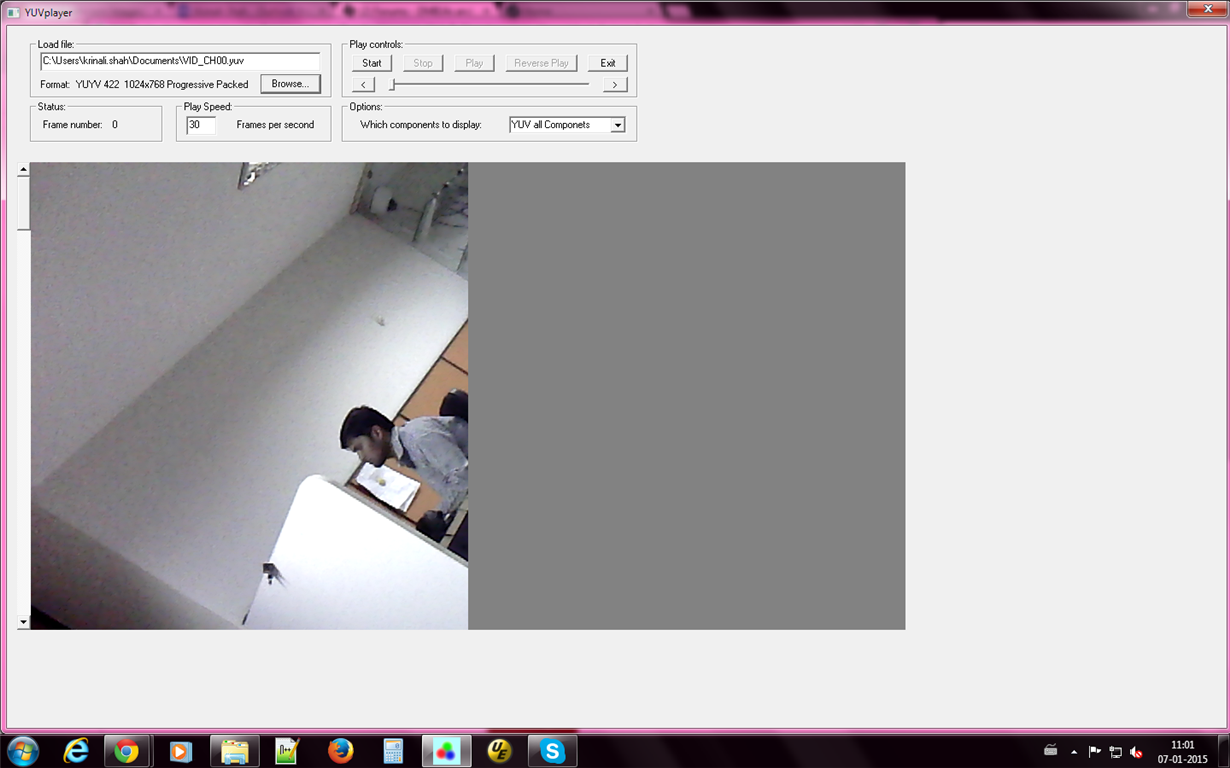
    By configuring CAPTURE_MODE := DDR, I was able to capture and dump a frame on A8.

    But in this frame dump, I get only half of the width of my actual resolution. My capture resolution is XGA(1024x768). But In a frame, I get only 512x768 pixels of data and rest half of the frame is shown as gray frame. Height is coming properly. Only width is a problem.

    Please find attached image file for your reference.

    I have verified that my sensor is giving 1024x768 size of frame data, by testing the sensor with our old camera board (Based on DM6446).

    So, What could be the issue here?

    Please provide some suggestions.

    Regards,

    Krinali Shah

  • Hi,


    Pl. check if the 'pCameraOutPrm->dataFormat = SYSTEM_DF_BAYER_RAW;' for the camera link.


    regards,

    Anand